Complete Calibration in Eye to Eye Scenario
This how-to guide introduces how to complete the hand-eye calibration in the Eye to Eye scenario.
|
For more information about calibration in the Eye to Eye scenario, please refer to Eye to Eye Calibration. |
Preparation before Calibration
Before hand-eye calibration, you need to finish the following preparations:
-
Construct the Mech-Mind Vision System.
-
Prepare the materials required for calibration.
-
Adjust the effect of calibration board’s point cloud.
-
Complete the robot and communication configuration.
Construct the Mech-Mind Vision System
Construct the Mech-Mind Vision System by referring to the section Construct Mech-Mind Vision System.
You need to use Mech-Eye Viewer, Mech-Center, Mech-Vision and Mech-Viz during hand-eye calibration. Please ensure that they have been installed and are running the latest versions.
Prepare the Materials Required for Calibration
The hand-eye calibration in the Eye to Eye scenario needs to use the calibration board. Please prepare the calibration board according to the following requirements:
-
Ensure that the circles of the calibration board are clearly visible and without obvious scratches, and the board does not suffer from deformations.
-
In the Eye to Eye scenario, mount the robot-specific bracket for calibration board onto the robot flange, and then mount the calibration board onto the bracket. Make sure that the calibration board is attached securely, and that the board is parallel to the XY plane of the robot flange frame.
If an undetachable gripper is connected to the robot flange, you can attach the calibration board directly to the gripper.
In addition, before calibration, move the robot to the starting point for calibration, that is, the bottom middle of the overlapped area of the two cameras’ field of view.
Adjust the Effect of Calibration Board’s Point Cloud
-
Open Mech-Eye Viewer to adjust camera parameters.
-
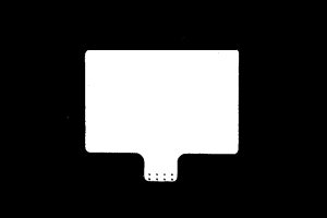
Adjust 2D parameters to make sure that the 2D image of the calibration board is clear and neither overexposed nor underexposed.
-
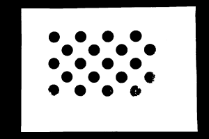
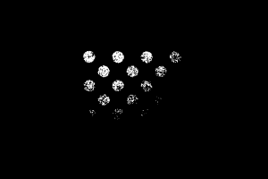
Adjust 3D parameters to make sure that the point clouds of the circles on the calibration board are complete and have clear contours. It is recommended to set Point Cloud Smoothing and Outlier Removal to Normal in the Point Cloud Processing section to reduce the point cloud fluctuation range.
If the on-site ambient lights are not ideal and affects the quality of 2D images and point clouds, you can use shading or supplemental light to improve the lighting conditions.
-
Make sure that the images and point cloud of the calibration board are up to standard after completing preceding steps.
Normal Overexposed Underexposed 2D image
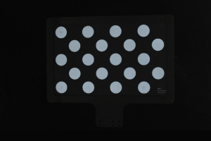
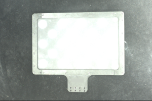
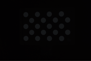
Point cloud
Pre-calibration Configuration
If the robot supports Standard Interface or Master-control, please complete pre-calibration configuration according to the section Pre-calibration Configuration for automatic calibration in the Eye to Hand scenario.
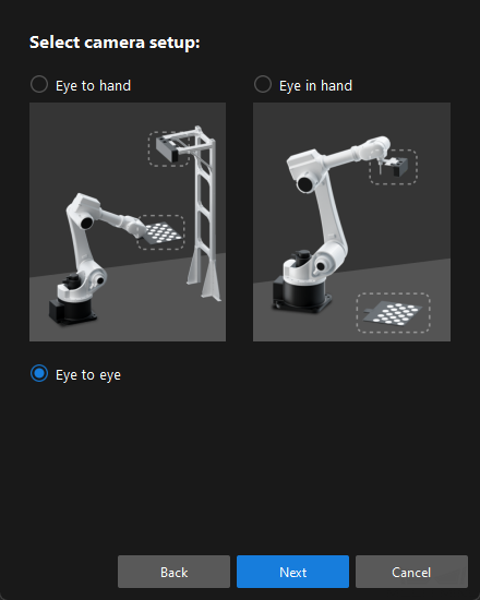
Compared with the automatic calibration in the Eye to Hand scenario, the following operation is different. During the pre-calibration configuration in the Eye to Eye scenario, you need to select the Eye to eye radio button in the Select camera setup window.
If the robot does not support Standard Interface or Master-control, please complete pre-calibration configuration according to the section Pre-calibration Configuration for manual calibration in the Eye to Hand scenario (using the multiple random calibration board poses method).
Compared with the preceding calibration process, the following operations are different during the pre-calibration configuration in the Eye to Eye scenario:
-
In the Select camera setup window, select the Eye to eye radio button.
-
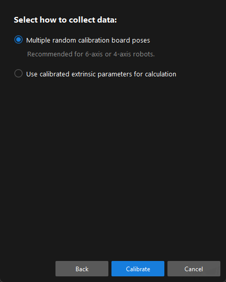
In the Select how to collect data window, select the Multiple random calibration board poses radio button.
Calibration Procedure
Connect to the Camera
-
In the Connect to camera step, select the camera to connect in the Detected cameras list, and then click the
 button or double-click the camera entry to connect to it.
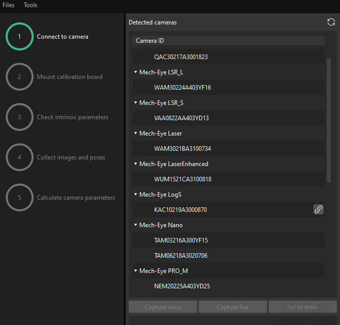
-
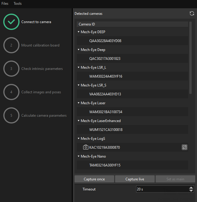
Repeat the preceding step to connect to the main camera. After the main camera is connected, the
 icon will be displayed before the camera ID.
To switch the main camera, select a camera, and then click the Set as main button.
-
After the camera is connected, click the Capture once or Capture live button.
-
In the right Image viewer panel, ensure that the captured 2D image and depth map meet the calibration requirements and click the Next button on the bottom bar.
-
If the captured image does not meet the calibration requirements, you need to open the Mech-Eye Viewer software to adjust the 2D and 3D exposure parameters and re-capture images.
-
In this step, the 2D image and depth map are captured only for the main camera. To confirm the effects of the images captured by the sub-camera, you can switch it to the main camera, and switch the original main camera back to the main camera after confirming.
-
Other Steps
If the robot supports Standard Interface or Master-control, please complete remaining steps of the calibration procedure according to the section Calibration Procedure for automatic calibration in the Eye to Hand scenario.
If the robot does not support Standard Interface or Master-control, please complete remaining steps of the calibration procedure according to the section Calibration Procedure for manual calibration in the Eye to Hand scenario (using the multiple random calibration board poses method).
|
Till now, the calibration process is completed.
Calculate Pose Relationship between Cameras from the Calibrated Extrinsic Parameters Directly
After calibrating the extrinsic parameters of the two cameras separately, you can use the Eye to Eye calibration procedure to calculate the pose relationship of the two cameras.
To do so, follow these steps:
-
Open Mech-Vision, and click the Camera Calibration (Standard) button in the toolbar. The Configuration before Calibration window will be prompted.
-
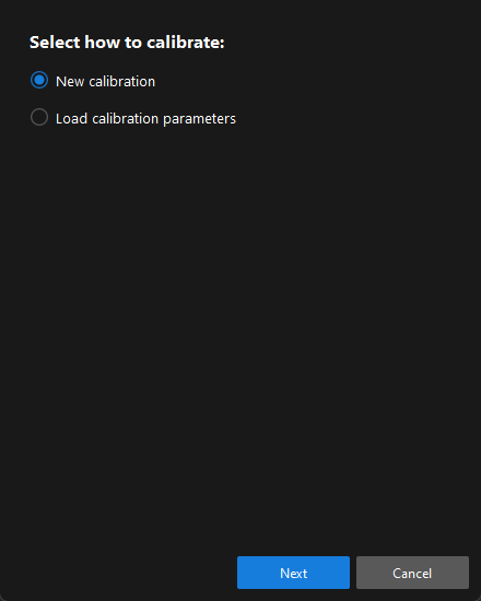
In the Select how to calibrate window, select the New calibration radio button, and then click the Next button.
-
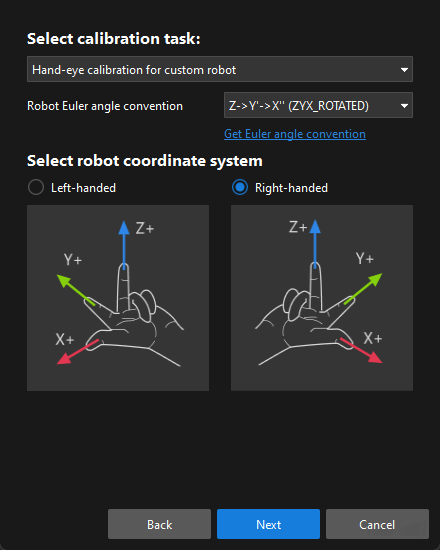
In the Select calibration task window, select Hand-eye calibration for custom robot from the drop-down list box, specify the Robot Euler angle convention parameter, select the robot coordinate system type, and then click the Next button.
-
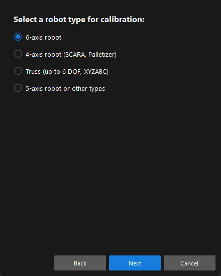
In Select a robot type for calibration window, select a robot type among 6-axis robot, 4-axis robot (SCARA, Palletizer) or 5-axis robot or other types radio button, and then click the Next button.
-
In the Select camera setup window, select the Eye to eye radio button, and then click the Next button.
-
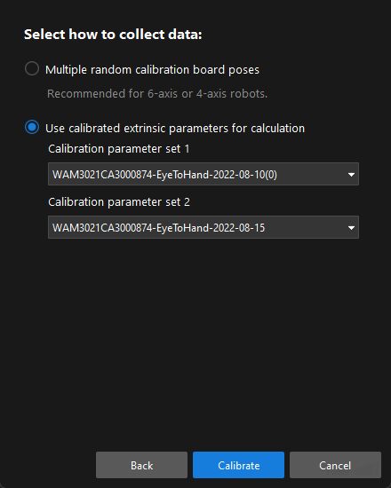
In the Select how to collect data window, select the Use calibrated extrinsic parameters for calculation, choose two camera’s extrinsic parameter files, and then click the Calibrate button. The Calibration (Eye to Eye) window will be prompted.
-
In the Connect to Camera window, find the camera to connect in the Detected Cameras list, and click
. -
Repeat the preceding step to connect to the second camera, and then click the Next button on the bottom bar.
-
In the Calculate camera parameters step, select the Calculate rotation and translation separately checkbox, and then click the Calculate camera extrinsic parameters button.
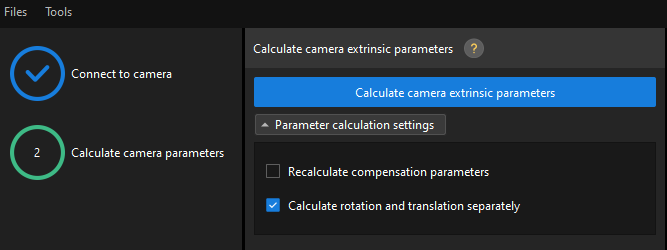
After the camera extrinsic parameters have been calculated, you can view the fused point cloud in the Point cloud viewer panel.
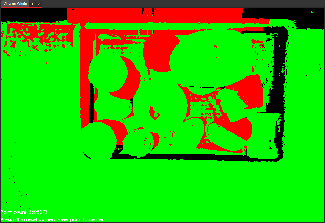
Check the Fusion Effect of Eye to Eye Calibration in a Mech-Vision Project
You can build a project as shown in the following figure. Note that the "Trigger Control Flow Given No Output" and "Trigger Control Flow Given Output" options in Execution Flags area should be selected.
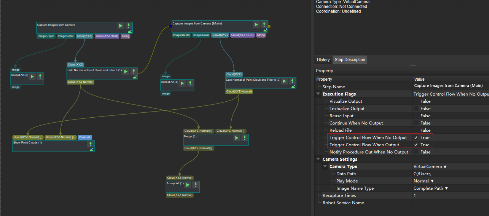
Execute the single Step "Merge Data" to display the fused point cloud. The point cloud output after merging is the fused whole point cloud, as shown in the figure below. You can click the upper left corner View as Whole| 1 | 2 to switch point clouds.