Depalletizing Vacuum Gripper (Multi-Pick)
The following parameters can be adjusted when the vacuum gripper is used for multi-pick depalletizing.
Box Grouping/Grouping Strategy
In multi-pick depalletizing mode, multiple adjacent boxes will be considered as a group, and boxes that belong to the same group will be picked at the same time.
Three grouping strategies are provided, which are Default, Group along Box Frame Axis, and Group along Custom Frame Axis.
Group along Box Frame Axis
One box will be used as the reference, and other adjacent boxes along the axis of the reference frame of this box will be grouped.
Grouping Direction
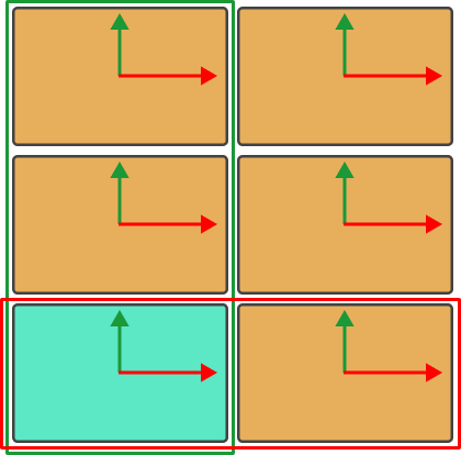
Select the axis along which the boxes will be grouped. If Along X-Axis (red axis in the figure) is selected, the two boxes in the red frame will be grouped. If Along Y-Axis (green axis in the figure) is selected, the three boxes in the green frame will be grouped.
Group Row Count Upper Limit
For some multi-pick depalletizing scenarios, multiple rows of boxes should be picked altogether. This parameter specifies the allowable maximum number of rows in one box group. The rows in the group calculated by the software will be as close as possible to the set upper limit.
Spacing Upper Limit
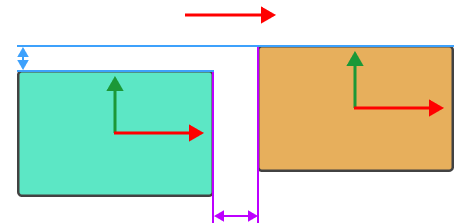
This parameter limits the maximum distance between two adjacent boxes in the grouping direction, which is the range indicated by the purple arrows in the figure below. When the distance is smaller than this value, the boxes can be considered to be in a group.
Deviation Upper Limit
This parameter limits the maximum deviation distance of a box in the direction perpendicular to the grouping direction, which is the range indicated by the blue arrows in the figure below. When the deviation distance is smaller than this value, the box can be considered to be in the group.
Angle Deviation Upper Limit
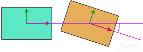
This parameter limits the rotation deviation angle of a box relative to the grouping direction. When the rotation angle is smaller than this value, the box can be considered to be in the group.
Only Group Complete Row
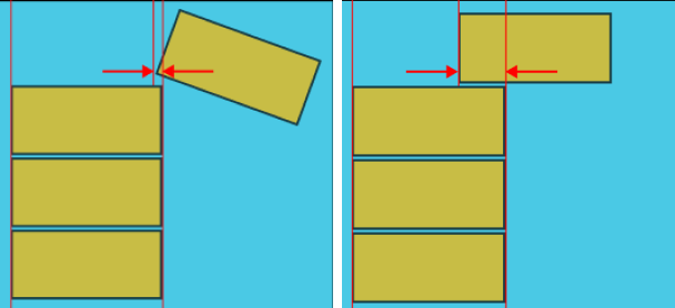
In actual applications, a complete row of boxes might be neglected because there are part of other boxes at ends in the grouping direction. Setting an Obstruction Tolerance Distance can preclude the intruding box from affecting the grouping result.
Obstruction Tolerance Distance
For a box group, if any other box intrudes in the direction perpendicular to the grouping direction, and the intrusion distance is smaller than this threshold, the intruding box will be ignored, and the box group will be considered a complete row. Otherwise, the box group will be discarded. The set value of Obstruction Tolerance Distance cannot exceed the edge length of the boxes.
Group along Custom Frame Axis
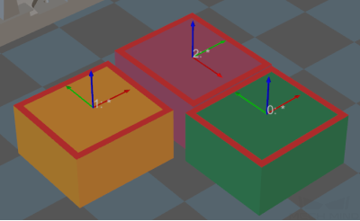
As shown in the figure below, if the 7 boxes are grouped along the axis in box reference frame:
-
The possible groups along X-axis of the box are: [1,2], [3,4], 5, 6, 7.
-
The possible groups along Y-axis of the box are: [1,3], [2,4], [5,6,7].
If you want the boxes to be grouped into [1,2], [3,4], [5,6,7], all boxes should be grouped along the direction indicated by the red arrow at the bottom of the figure. The red arrow is an axis of a custom reference frame.
X/Y/Z Coord. of Custom Frame Origin
Enter values to specify an origin of the custom reference frame.
Group Row Count Upper Limit
For some multi-pick depalletizing scenarios, multiple rows of boxes should be picked altogether. This parameter specifies the allowable maximum number of rows in one box group. The rows in the group calculated by the software will be as close as possible to the set upper limit.
Box-Frame Angle Threshold
Before the boxes are grouped, the angle between the box reference frame and the custom reference frame will be calculated. If the angle exceeds this threshold, the corresponding box will not be grouped.
Spacing Upper Limit
This parameter limits the maximum distance between two adjacent boxes in the grouping direction, which is the range indicated by the purple arrows in the figure below. When the deviation distance is smaller than this value, the box can be considered to be in the group.
Deviation Upper Limit
This parameter limits the maximum deviation distance of a box in the direction perpendicular to the grouping direction, which is the range indicated by the blue arrows in the figure below. When the deviation distance is smaller than this value, the box can be considered to be in the group.
Angle Deviation Upper Limit
This parameter limits the rotation deviation angle of a box relative to the grouping direction. When the rotation angle is smaller than this value, the box can be considered to be in the group.
Only Group Complete Row
In actual applications, a complete row of boxes might be neglected because there are part of other boxes at ends in the grouping direction. Setting an Obstruction Tolerance Distance can preclude the intruding box from affecting the grouping result.
Obstruction Tolerance Distance
For a box group, if any other box intrudes in the direction perpendicular to the grouping direction, and the intrusion distance is smaller than this threshold, the intruding box will be ignored, and the box group will be considered a complete row. Otherwise, the box group will be discarded.
Suction Cup Offset/Offset Strategy
When the vacuum gripper is used for box depalletizing, the vacuum gripper is fixed and cannot be changed in most cases. However, the vacuum gripper should be used to pick boxes of varied dimensions. To avoid picking non-target boxes in depalletizing, the robot may not pick the target box with the center of the vacuum gripper. Instead, the corner or other parts of the vacuum gripper will be used.
There are three offset strategies, i.e., Default Strategy, Custom Strategy Priority, and By Edge/Corner ID Sequence.
Default Strategy
When this strategy is adopted, the corners of the vacuum gripper will be prioritized for picking boxes.
Custom Strategy Priority
When this strategy is adopted, you can assign priorities to three strategies.
Strategy Priority
There are three available strategies, i.e., CenterToCenter, EdgeMidpointToEdgeMidpoint, and CornerToVertex. Please assign priorities to these strategies according to the actual requirement.
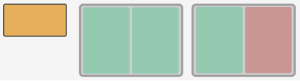
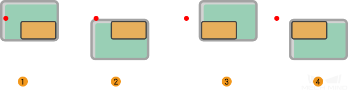
In the figure below, the orange rectangle represents the box, and the gray rectangle represents the vacuum gripper. The green part of the vacuum gripper indicates that the section is activated, while the red part indicates that the section is deactivated.
-
When a single section is activated
The figures below demonstrate the effects of using CenterToCenter, EdgeMidpointToEdgeMidpoint, and CornerToVertex from left to right.
-
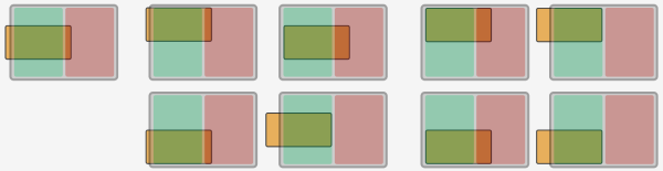
When both sections are activated
The figures below demonstrate the effects of using CenterToCenter, EdgeMidpointToEdgeMidpoint, and CornerToVertex from left to right.
-
The effect is similar when there are more than two activated sections of the vacuum gripper.
Box Surface Coverage Lower Limit
This parameter specifies the minimum proportion of a box’s upper surface covered by the vacuum gripper when the vacuum gripper attempts to pick a box. If the coverage is larger than the value, it is considered that the vacuum gripper is able to pick the box.
Suction Cup Orientation
This parameter specifies the orientation of the vacuum gripper relative to the box group during picking.
You can set the Suction Cup Long Edge Orientation and Orientation Reference, and there are four relative positional relationships in total:
-
The long edge of the vacuum gripper is parallel to the long edge of the box group.
-
The long edge of the vacuum gripper is perpendicular to the long edge of the box group.
-
The long edge of the vacuum gripper is parallel to the direction along which the boxes are grouped.
-
The long edge of the vacuum gripper is perpendicular to the direction along which the boxes are grouped.
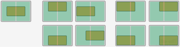
The figure on the left shows the effect when the long edge of the vacuum gripper is parallel to the long edge of the box group, and the figure on the right shows the effect when the long edge of the vacuum gripper is perpendicular to the long edge of the box group.
Offset Priority
You need to set a reference point to enable this feature. The offset strategies will be sorted according to the distance between the TCP and the reference point, and the offset strategy with a TCP closer to the reference point has a higher priority. Once Sort by Distance to Reference Point is selected, the following parameters will appear.
Reference Point X/Y
Specify the position of the reference point. The reference point will appear in the 3D simulation area.

By Edge/corner ID Sequence
When this strategy is adopted, the vacuum gripper will pick by using the edges/corners that have been specified by the user with different priorities.
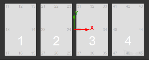
The edge/corner IDs are generated automatically in the vacuum gripper configurator. The two-digit numbers at the edge of each section are edge/corner IDs, as shown below.
Box Surface Coverage Lower Limit
This parameter specifies the minimum proportion of a box’s upper surface covered by the vacuum gripper when the vacuum gripper attempts to pick a box. If the coverage is larger than the value, it is considered that the vacuum gripper is able to pick the box.
Fixed Edge Corner Label Numbers
Specify the sequence of the edge/corner IDs. For example, enter 11, 17, 21, and 22, and the vacuum gripper will pick by using the corresponding edge/corner according to the sequence you specified.
Suction Cup Orientation
This parameter specifies the orientation of the vacuum gripper relative to the box group during picking.
You can set the Suction Cup Long Edge Orientation and Orientation Reference, and there are four relative positional relationships in total:
-
The long edge of the vacuum gripper is parallel to the long edge of the box group.
-
The long edge of the vacuum gripper is perpendicular to the long edge of the box group.
-
The long edge of the vacuum gripper is parallel to the direction along which the boxes are grouped.
-
The long edge of the vacuum gripper is perpendicular to the direction along which the boxes are grouped.
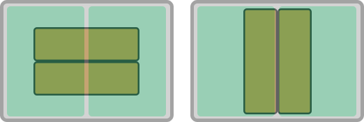
The figure on the left shows the effect when the long edge of the vacuum gripper is parallel to the long edge of the box group, and the figure on the right shows the effect when the long edge of the vacuum gripper is perpendicular to the long edge of the box group.
Carton Drop Detection
In actual box depalletizing projects, DI check points will be added to the working surface of the suction cups to monitor whether the boxes are dropped during picking and placing by comparing the sensor signal changes.
After the DI check points are added to the vacuum gripper configurator, the software will determine which sensors on the working surface of the vacuum gripper are covered by the picked boxes, and therefore the DI signals that should be detected can be confirmed.
Dist from Carton Edge To Remove DI
When DI check points are used in the carton drop detection and DI check points are at the edge of the carton, the software may mistakenly detect that the carton is dropped due to picking deviation, loose suction at the edge, deformation of the carton, or other reasons. Under such circumstances, you can set a Dist from Carton Edge To Remove DI to remove DI check points at the edge of the carton to avoid detection errors. The red frames shown in the figure below represent the edge area where the DIs are removed.
Count of Picked Workobjects
| Limit Total Count |
Limit the number of total picked objects. |
| Planned Count |
The maximum number of total picked objects. |
| Total Count of Picked |
The number of objects that have been already picked. |
| Count of Picked This Time |
The number of objects picked this time. |
| Set Count Each Time |
Specify the number of objects to be picked at a time. |
| Limit Count Each Time |
Specify the maximum number of objects to be picked at a time. The maximum number of objects or fewer objects can be picked at a time. |