Update Scene Objects
Function
Update the pose and dimensions of the specified scene object via the vision service or parameter settings.
Usage Scenario
When running a Mech-Viz project, the position and dimensions of the scene object should be adjusted in order to avoid collisions in different situations.
Parameter Description
General Parameters of Non-Move Steps
Skip Execution
| None |
Default setting. Do not skip the current Step. |
| Simulation only |
Skip the current Step during simulation. The exit port is specified by Out Port When Skip. |
| Always |
Skip the current Step when the project is simulating or running. The exit port is specified by Out Port When Skip. |
| Instruction |
When Simulation only or Always is selected, the current Step will be skipped and the subsequent Step will be executed when running the project. If this parameter is set to None in “Check DI” Step in the project, and there is no external input signal during simulation, the project will be stopped when executing to this Step. In this case, setting the parameter to Simulation only or Always enables the simulation to continue. |
Update Info Source
This parameter specifies the information source to update the scene object’s pose and dimensions. The two supported information sources are Config Value and Vision Service.
Config Value
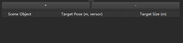
+: Add a new scene object.
-: Delete the selected scene object.
You can add or delete a scene object according to the actual requirement. The pose and dimensions of the scene object at the top of the Scene Object list will be updated first. For each item in the Scene Object list, you can select the scene object in the corresponding drop-down list and then specify the Target Pose and Target Size. The format of target pose should be XYZ (m) plus quaternions and the target size is the dimensions in X, Y, and Z-directions in meters.
For example, a target pose can be 1.00, 0.00, 0.00, 1.00, 0.00, 0.00, 0.00, a target size of a cuboid can be 0.40, 0.40, 1.00 (length, width, height), and a target size of a vertical cylinder can be 0.50, 1.00, 0.00 (radius, height, 0).
Vision Name
Select the Mech-Vision project that provides the vision service. The Mech-Vision project must be a registered one.
Once you selected a Mech-Vision project, please follow the steps below to configure the Procedure Out Step in the Mech-Vision project.
-
Go to the Step Parameters panel, and set the Port Type to Custom.
-
Click Set data type output to external communication, and the Procedure Out Setting Assistant window will pop up.
-
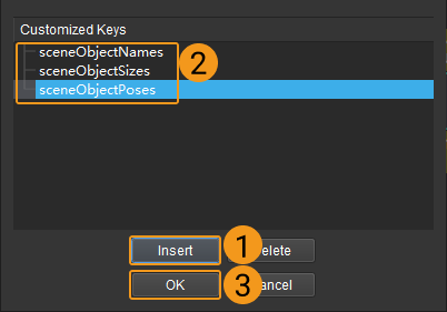
Click Insert to create 3 customized keys.
-
Double-click the customized keys to rename them to sceneObjectNames, sceneObjectSizes, and sceneObjectPoses.
-
Click OK to save the changes.
-
Connect the input port of Procedure Out with corresponding output ports respectively.
| Customized Keys | Description |
|---|---|
sceneObjectNames |
The name should be consistent with that of the scene object in Mech-Viz. |
sceneObjectSizes |
Object dimensions in meters, (length, width, height) for cuboids and (radius, height, 0) for cylinders. |
sceneObjectPoses |
XYZ (m) plus quaternions. |
Example
In a scenario where a sensor door is used, this Step is used to update the model of the door, thus collisions in different processes can be avoided. Config Value is used to update the scene object in this example.