Adapter Generator Guide
This topic introduces the Adapter Generator and shows how to generate an Adapter program rapidly.
Introduction to the Adapter Generator
Adapter Generator is a built-in component of Mech-Center. It applies to scenarios where vision results are provided by Mech-Vision only and a TCP/IP Socket is used for the communication.
With the Adapter Generator, you can:
-
Generate an Adapter program rapidly and create an Adapter project.
-
Learn how to program Adapter to meet complex actual requirements.
Select to open the Adapter Generator and follow the instructions to set it up.
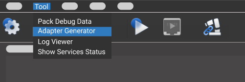
| The Adapter Generator is only available in the Administrator mode. |
Generate an Adapter Program Rapidly Using the Adapter Generator
| During configuration, you can hover the cursor over the options to view the tooltips. |
Network Config – Server or Client
Set the parameters Adapter name, Adapter’s role, and Stream Format in this step.

Parameter description:
-
Adapter name: specifies the name of the Adapter program.
-
Adapter’s role: specifies the Adapter as a server or client of the TCP/IP Socket communication. If the Adapter functions as a client and there is a port restriction on the server, please select the Bind Port checkbox.
To ensure successful communication with the peer, please make sure the host address is configured correctly in Deployment Settings. Please refer to Deployment of an Adapter Project for detailed instructions. -
Stream Format: specifies the format for data transmission. ASCII string and HEX are supported. If “HEX” is selected for Stream Format, you will need to choose between “Big endian” and “Little endian”.
Mech-Viz/Mech-Vision Config – Poses and JPs
|
| As the workflow of check_collision example project, the Step “Vision Look” triggers the camera to capture images. Non-move-type Steps must be included in the workflow. Please do not modify the names of Steps (notify_1, notify_2 and visual_look_1), or else an error may occur. |
In this step, configure parameters related to Mech-Viz and Mech-Vision projects.
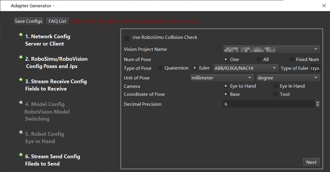
Description of parameters related to Mech-Vision:
-
Mech-Vision project name: select the Mech-Vision project name. Select the Mech-Vision project that communicates with Adapter in the drop-down list.
-
Num of poses: select the number of poses to be sent to the peer device.
-
Pose type: select whether to use quaternions or Euler angles to represent the poses.
-
Pose units: the unit used for the poses; usually in millimeter and degree.
-
Camera installation: chooses the camera installation methods, including ETH and EIH.
-
Reference frame of poses: specifies the reference frame of the sent poses. The robot base reference frame is usually used as the reference frame of poses. For scenarios using EIH, when the pose of robot flange cannot be provided, only the tool reference frame can be used.
-
Decimal precision: the precision of the pose data. The maximum number of decimal places is 10.
Description of parameters related to Mech-Viz:
-
Use Mech-Viz for collision detection: select this option to detect collisions on the vision points through the Mech-Viz project. Pick points from unsuccessful planning will be filtered, and collision-free pick points will be kept.
-
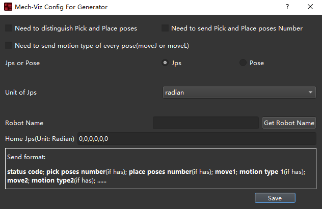
Mech-Viz Config: this option is only available when Use Mech-Viz for collision detection is selected. Click this button to open the Mech-Viz Config For Generator window. After configuring relevant parameters, click Save.
-
Need to distinguish Picking and Placing Poses: the picking pose refers to all poses before the Vision Move Step (including the pose of Vision Move Step), and the place pose refers to poses after the Vision Move Step. In some scenarios, the robot may need to distinguish the picking and placing actions according to the task.
-
Need to send Pick and Place poses Number if there are many targets, the number of poses can be sent as well. When it is selected, the field will be sent by default when the number of vision targets is greater than 1.
-
Need to send motion type of every pose(moveJ or moveL): the motion type of the move-type Steps in Mech-Viz, including moveJ and moveL.
-
Update Code: the code for moveJ is 1, and the code for moveL is 2 by default. You can also customize the code. After modification, click Update Code to apply the settings.
-
Jps or Pose: the format of the poses; Jps is selected by default.
-
Unit of Jps/Unit of Pose: when Jps is selected, degree is usually used as the unit. When Pose is selected, and the pose is represented by quaternions, millimeter is usually used as the unit.
-
Robot Name: name of the robot service. The simulated robot in Mech-Viz should be based on a real robot. Adapter will simulate the service of the real robot. Please make sure the robot name here is the same as the one in Mech-Viz. Click Get Robot Name to autoload the name of the robot.
-
Home Jps(Unit: Radian): set the home position of the robot in Mech-Viz. The unit is radians. Please use commas to connect the numbers. You can add a “Fixed-Point Move” Step in the workflow of Mech-Viz and set its JPs as the home position, and then copy the JPs.
Stream Receive Config – Fields to Receive
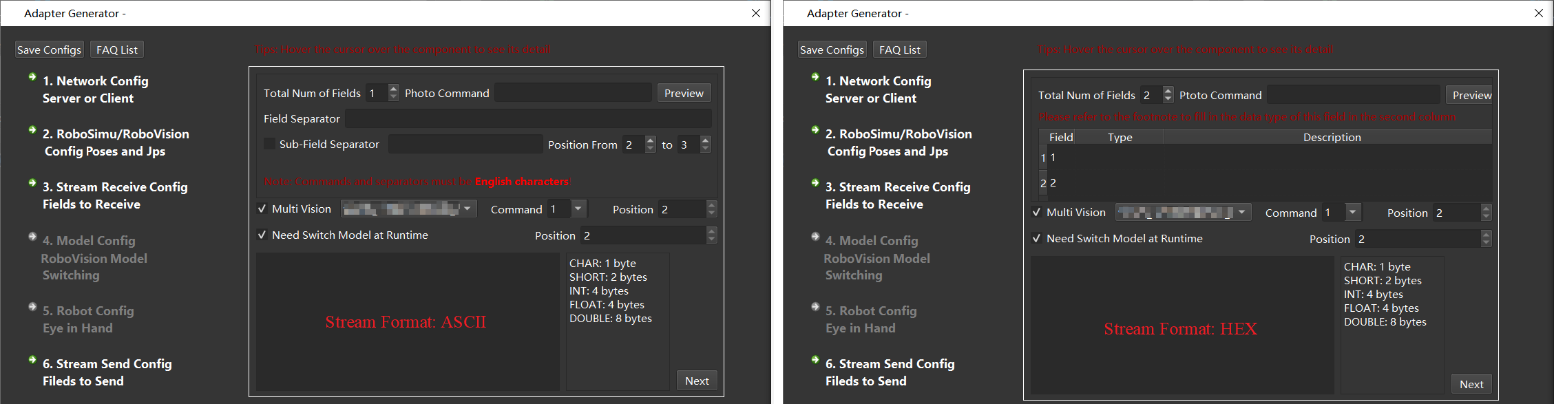
In this step, set the format of the fields to receive, including photo command, multiple projects (instruction code), dynamically switch templates (template instruction code), as well as the total number of fields, field types, field separators and sub-field separators. After the configuration, click Next.
-
Total Num of Fields: the number of parameters that need to be set, and the value range is 1~10. There must be a photo command in the field.
-
Photo Command: the photo command sent from external devices to Mech-Mind Software Suite, which triggers the camera to capture images. When the stream format is ASCII string, it is recommended to use English letters to represent the command. For example, use letter p as the command and the field position is 1 by default. When the stream format is hexadecimal (HEX), an integer in hexadecimal format is required, such as 0xff or ff.
-
Field Separator and Sub-Field Separator: only need to be set when the communication format is ASCII string. If there are more than two fields, you need to fill in the field separator; if there are additional separators in the additional information, the sub-field separator is also necessary, and you can specify the start and end range of the sub-field.
-
Field Type and Description: needs to be set when the communication format is hexadecimal (HEX). The available types are CHAR, SHORT, INT, FLOAT, and DOUBLE. You can describe the function in the Description.
-
Multi Vision: This setting is optional. When there are multiple Mech-Vision projects in an application, different Mech-Vision projects need to be called according to external commands, and the command codes are configurable.
The command code and the field position of each project should be unique.
Robot Config – Eye in Hand
| This step is only available when Camera Installation is set to Eye In Hand in the previous Mech-Viz/Mech-Vision Config – Poses and JPs step. |
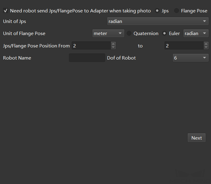
Set the robot pose where to capture images in this step and then click Next.
Parameter description:
-
Need robot send Jps/Flange Pose to Adapter when taking photo: if the object pose in the robot base reference frame needs to be sent to the peer device, JPs or flange pose when the robot captures images are needed. After this option is selected, you can select between JPs and flange pose.
-
Unit of Jps: unit of joint positions; radian and degree are supported.
-
Unit of Flange Pose: unit of the flange pose. Quaternions and Euler angles are supported. When Quaternion is selected, millimeter and meter are available units; when the pose is represented by Euler angles, millimeter and degree are unavailable units.
-
Jps/Flange Pose Position From: It is the position of the start and end fields of the pose in the total field.
The index position starts counting from 1, and the index position 1 is the camera instruction! -
Robot Name: the name used to identify the robot service, which needs to be consistent with the robot name in Mech-Viz.
-
Dof of Robot: the degree of freedom of the robot. Only 4-axis and 6-axis robots are supported currently. Please select the corresponding robot’s degree of freedom according to the actual project.
Stream Send Config – Fields to Send
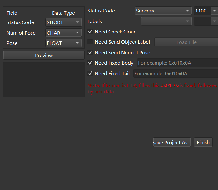
Set the format of the poses to be sent in this step and then click Next.
Parameter description:
-
Field Separator and Sub-Field Separator: sets the separator. They are needed to be set only when the stream format is ASCII. If there are more than two fields, you need to fill in the field separator; if there are additional separators in the additional information, the sub-field separator is also necessary, and you can specify the start and end range of the sub-field.
-
Status Code: sets the sending status, each status corresponds to a unique status code.
-
Need Check Cloud: After it is selected, the point clouds will be checked, if the point clouds do not exist, the corresponding status code will be output.
-
Need Send Object Label: Sending object labels means sending to the peer device according to the label recognized by Mech-Vision, each label is connected to the Pose; when the peer device is inconvenient to parse the label string, you can also specify the code of the corresponding label, which needs to load the label file of all label strings. It should be noted that the label file format must be in JSON array format.
-
Need Send Num of Pose: sets the number of poses to send each time.
-
Need Fixed Body: sets the message sent to the peer device (the message after the error code) when the vision recognition fails.
-
Need Fixed Tail: After it is selected, a fixed tail mark will be added after the data.
| When the stream format is hexadecimal (HEX), it is necessary to set the status code, the number of poses, and the numeric type of poses. |
After configuring all the above settings, click Finish or Save project as to save the Adapter project. After saving the Adapter project, please refer to Deployment of an Adapter Project for instructions on how to deploy the Adapter project.
For more information about programming and development of Adapter, please read: