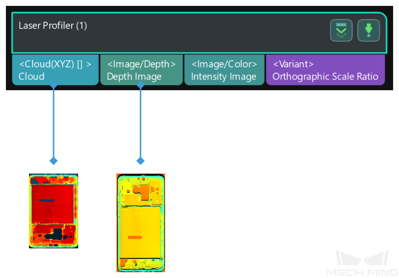
3D Laser Profiler
Function
This Step can control 3D laser profiler (hereinafter referred to as laser profiler) to acquire data by using Mech-Vision.
|
Currently, this Step is only available for Mech-Eye 3D Laser Profiler and SSZN 3D Laser Profiler. |
Usage Scenario
This Step is usually used as the initial input for a vision project. This Step is suitable for the inspection and measurement applications in industries include consumer electronics, EV battery, automobile, and home electronics with a high requirement for precision.
Usage Instructions
This Step should be used in conjunction with Mech-Eye Viewer. The usage instruction is as follows.
-
Connect the laser profiler in Mech-Eye Viewer.
-
Adjust the parameters and save the parameter group in the Profile Mode and Scan Mode.
-
Profile Mode: Adjust the exposure time, analog gain, digital gain or laser power to ensure a good quality of the profile, intensity image and depth map.
-
Scan Mode: Adjust “Trigger setting” and “Scan setting” to prepare for collecting images.
-
-
Set the IP address of the selected laser profiler, and select the saved parameter group in the Mech-Vision.
-
Adjust the parameters of the “3D Laser Profiler” Step in the Mech-Vision.
-
Run the Step.
Parameters
- Laser Profiler Model
-
Parameter description: This parameter is used to select the laser profiler model you want to use.
Value list: LNXCamera, SSZNCamera
Default value: LNXCamera
Tuning instruction: If you need to use Mech-Eye 3D Laser Profiler, please select “LNXCamera.” If you need to use SSZN 3D Laser Profiler, please select “SSZNCamera.”
Basic Settings
- IP Address
-
Parameter description: The IP address of the laser profiler.
Tuning instruction: Click Open the editor, and select the laser profiler that you want to use and its IP address in the pop-up window. After selecting OK, the IP address will be automatically filled in this parameter frame.
- Parameter Group
-
Parameter description: This parameter is used to select the parameter group used in the laser profiler.
Trigger Settings
- Data Acquisition Trigger Source
-
Parameter description: This parameter is used to select the source of the signals that trigger data acquisition. In one round of data acquisition, multiple lines are scanned, multiple profiles are generated, and one intensity image and one depth map are generated using the profile data.
Value list: External, Software.
Tuning instruction: If you use externally input signals to trigger data acquisition, select “External.” Otherwise, select “Software.”
- Line Scan Trigger Source
-
Parameter description: This parameter is used to select the source of the signals that trigger the scan of a single line.
Value list: Encoder, Fixed rate.
Tuning instruction: If you use an encoder to trigger scanning, select “Encoder.” If you need to trigger scanning at a fixed rate, select “Fixed rate.”
- Scan Line Count
-
Parameter description: This parameter is used to set the number of profiles needed to generate one intensity image/depth map.
Default value: 1600
Tuning instruction: Make sure that the set value can cover one target object completely.
- Scan Duration
-
Parameter description: This parameter is used to set the duration for each round of data acquisition (in ms). The profiles acquired in this duration will be used to generate one intensity image/depth map.
Default value: 5000 ms
- Y-Axis Resolution
-
Parameter description: This parameter is used to set the resolution in the Y direction, which is the distance between two neighboring points along the travel direction of the target object.
- Trigger Interval
-
Parameter description: This parameter is used to set the number of trigger signals needed for scanning one line.
- Pulse Equivalent
-
Parameter description: This parameter is used to set the distance or displacement (in mm) represented by an encoder signal period.
Default value: 0.004000 mm
Tuning instruction: This parameter is related to the encoder hardware specifications.
Other Settings
- Movement Mode
-
Description: This parameter is used to select the movement mode which determines how the object moves relative to the laser profiler.
Value list: One direction, Back and forth.
Tuning Instruction: Select the movement mode according to actual situation.
- X Direction Translation
-
Parameter description: When you select “Back and forth,” Mech-Vision will output multiple acquired point clouds that represent parts of the object, and therefore an entire point cloud of the object can be generated. This parameter is used to set the distance (in mm) between the data acquired from two scans on the X-axis.
Default value: 100.000 mm
Cache Setting
- Maximum Cached Data
-
Description: This parameter is used to show the maximum data volume that can be cached. With each scan, the cached data can generate depth maps, intensity maps, and point clouds. When this value is exceeded, you can process the cached data using the “Cache Overflow Solution” or manually clear the cache.
- Cache Overflow Solution
-
Description: This parameter is used to select the solution to the cache overflow.
Value list: Delete earliest acquired data, Pause current data acquisition.
- Clear Cache
-
Description: This parameter is used to clear cached image data manually.
