Vision Continue Palletizing
Function
This Step is used to continue to palletize on the pallet that has already been stacked with boxes by using “Vision Look” to recognize vacant positions.
Usage Scenario
This Step is used in scenarios where there is a relatively high requirement for space utilization (such as the 3D dimensional storehouse). You can merge the unfilled pallets.
| The relevant example project to the “Vision Continue Palletizing” Step is provided to help you learn more about the process of continuing the palletizing through vision. For the example project, you can go to File > New > Example projects > Box palletizing > Vision Continue Palletizing in the software. |
Parameter Description
Move-Type Step Common Parameters
Send Waypoint
Selected by default to send waypoint poses to the receiver, such as the robot. When this option is unselected, the waypoint pose will not be sent. However, the waypoint will remain in the planned path.
Try Continuously Running through Succeeding Non-Moves
Unselected by default. When non-move Steps, such as Vision Look, Set DO, Check DI, etc., are connected between move-type Steps, the robot’s path planning will be interrupted, and the actual robot will take a short pause, reducing the smoothness of running.
When this option is selected, the project will continue to run without waiting for the current move-type Step to complete execution, and therefore the robot can move in a smooth way without pauses. However, enabling this option may cause the execution of the Step to end prematurely.
Why will this option cause the execution of the Step to end prematurely?
Mech-Viz will send multiple poses simultaneously to the robot when the project is running. When the currently returned JPs of the robot correspond to the last pose sent by Mech-Viz, Mech-Viz will assume that the robot has moved to the last position.
For example, there are 10 move-type Steps in a path, and the pose of the 5th move-type Step is the same as that of the last move-type Step. When the robot moves at low speed, it sends JPs to Mech-Viz when it moves to the 5th move-type Step, Mech-Viz may mistakenly determine that the robot has finished the move-type Steps and prematurely ends the Steps since the poses of the 5th move-type Step and the last move-type Step are the same in the path.
Do Not Check Collision with Placed Workobject
Unselected by default, namely that the collision with the already placed objects will not be detected. When this option is selected, the collisions between the robot, end tool, and placed objects will be detected.
In palletizing scenarios, the two possible cases of error are as follows:
-
When the robot is placing a carton, the robot may come into light contact with the placed cartons while no deformation will be caused. After Mech-Viz detects this collision in simulation, it will plan other positions for placing the carton, and therefore a full stack cannot be formed.
-
Usually, the TCP of a suction cup is inside the suction cup model instead of on the surface of it. Under this circumstance, the suction cup may be embedded in the model of the picked carton in the simulation of picking, while the software does not detect the collision between the end tool and the picked object. After the robot places the object and the carton model turns into an object model in the scene, a collision between the suction cup and the carton will be detected and the palletizing cannot be completed.
When this option is selected, no collision between the robot, end tool, and the placed object will be detected, and the above two cases of errors can be avoided.
Point Cloud Collision Detection Mode
Select the proper mode according to the requirement of the on-site situation. Usually, the default setting Auto can be used. Do not check collision mode can be used in move-type Steps before the robot picks the object, and Check collision mode can be used after the robot picks the object.
Auto |
Default setting. Collision with point cloud is checked only for the “Vision Move” Step and the “Relative Move” Step that depends on the “Vision Move” Step, but not for all move-type Steps. |
Do not check collision |
Point cloud collisions for all move-type Steps will not be detected. |
Check collision |
Point cloud collisions for all move-type Steps will be detected. |
| When is switched on, Mech-Viz will detect collisions between the robot model, end tool model, and point cloud when planning the path. Normally, Mech-Viz detects whether the robot collides with workobjects during picking and placing. When there are point cloud outliers, non-exiting collisions will be detected, which leads to errors in path planning. |
Ignore Workobject Symmetry
This parameter will only take effect when Waypoint type of the Step is set to Workobject pose.
None |
Default setting, i.e., do not disable symmetry on any axis. |
Around workobject frame Z axis |
Only disable symmetry on Z-axis of the workobject reference frame. |
Around workobject frame X&Y axis |
Disable symmetry on X-axis and Y-axis of the workobject reference frame. |
Around all axes |
Once the object symmetry is disabled, the robot will place the objects strictly according to the workobject poses. |
| In some special cases, objects are not pickable due to their peculiar poses. Setting Rotational symmetry under in Resources may solve this problem. Candidate poses of the recognized workobjects will be calculated according to the set rotational symmetry angle. When Mech-Viz plans to pick workpieces, if the default pose is not feasible for picking, the candidate poses will be tried. As the candidate poses calculated based on the settings of Rotational symmetry are different from the original poses output from Mech-Vision, the consistency of the objects’ place poses cannot be guaranteed. |
Plan Failure Out Port
Once this parameter is selected, a “Plan failure” exit port will be added to the Step.
During the planning process, planning is carried out along the branch after the “Success” exit port. If the planning fails in the current Step, the branch process after the “Planning failure” exit port will be executed.
Held Workobject Collision Detection Settings
Do Not Check Collision with Scene Object/Robot
Unselected by default. Once this option is selected, the collisions between the held workobject with the scene objects or robot will not be detected, and therefore the calculation workload of collision detection will be reduced, the planning speed can be increased, and the cycle time can be shortened. It is usually enabled in the first one or two move-type Steps after the robot picks the object.
Please enable this option cautiously as there may be collision risks.
When Detect collision between held workobject and others under is enabled, the software will detect whether the model of the held object collides with the models of the scene objects and the robot.
In palletizing projects, the calculated carton dimensions have millimeter-level errors with the actual dimensions, and frictions between cartons may occur during picking but no collisions will occur. For some move-type Steps that will obviously not cause collisions, detecting such collisions only adds to the calculation workload and planning time, and consequently extending the cycle time. In palletizing projects, enabling Do Not Check Collision with Scene Objects does not affect the collision detection between the held carton and the placed cartons. This option can be enabled when there are scene objects under the stack to avoid failure of finding the palletizing solution.
Do Not Check Collision with Point Cloud
Unselected by default. Once this option is selected, the collisions between the held workobject with the point clouds in the scene will not be detected, and therefore the calculation workload of collision detection will be reduced, the planning speed can be increased, and the cycle time can be shortened.
-
When both Detect collision between held workobject and others under and Configuration on point cloud ‣ Detect collision between point cloud and others are enabled, the software will detect whether the model of the held workobject will collide with the point cloud in the scene.
-
When Mech-Vision sends the point cloud and object model to Mech-Viz, the point cloud and the object model are fitted together. After the robot picks the object, the model moves along the planned path, and the collision between the model of the held workobject and the point cloud will occur.
-
It is known that the model of the held workobject will have false collisions with the point cloud. Detecting such collisions unnecessarily adds to the calculation workload and extends the planning time.
Visual Match
Match Max Dist Error
Specify the maximum allowable distance error between the box pose inherited from the palletizing Step and the box pose recognized by the vision service in the X and Y-axis direction. The matching fails if the value exceeds the threshold.
Z Dist Tol
Specify the maximum allowable distance error between the box pose inherited from the palletizing Step and the box pose recognized by the vision service in the Z-axis direction. The matching fails if the value exceeds the threshold.
Max Rot Correction
Specify the maximum allowable rotation error between the box pose inherited from the palletizing Step and the box pose recognized by the vision service around the Z-axis. The matching fails if the value exceeds the threshold.
Match Symmetry
In actual application, the box orientation provided by the vision service and the box orientation inherited from the specified pallet pattern may differ, resulting in a matching failure. This feature can be used to fix this problem.
| Option | Description |
|---|---|
Auto |
Use “Symmetry90Deg” when the difference between the sides of the boxes is less than 2 cm, and use “Symmetry180Deg” when the difference between the sides of the boxes is more than 2 cm. |
NoSymmetry |
No rotational symmetry will be applied. |
Symmetry180Deg |
Select this option when the XY-plane is a rectangle. |
Symmetry90Deg |
Select this option when the XY-plane is a square. |
Correction
Correction Type
After the vision matching is completed, correct the pose of the pallet pattern based on the average error of the matched box poses.
| Option | Description |
|---|---|
Total |
Correct both the translation error and rotation error. |
TranslationOnly |
Only correct the translation in the X-, Y- and Z-direction. |
RotationOnly |
Only correct the rotation around Z-axis. |
J
Box Label of Interest
Boxes are filtered based on labels provided by vision projects, and only those with the specified labels will be used for visual matching. If no object label is set, all boxes recognized by vision projects will be used for visual matching.
Check Placed Boxes Order
Select to check the order of the palletized boxes in the project.
The requirements for continuing palletizing are that the box serial number must be uninterrupted and that serial number 1 must not be empty. If these requirements are not met, an error will be reported.
Take the following pallet pattern for example: There are 9 boxes on one layer, and the picking order will be calculated automatically.
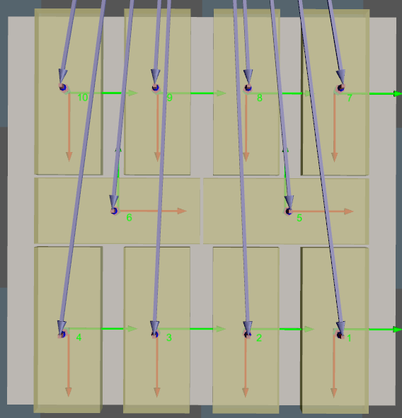
For the following situations:
-
If position indicated by 1 is not occupied with a box, and position 2 and 3 are occupied with boxes, an error will occur.
-
If positions indicated by 1, 2, 3, 4, and 6 are occupied, while position 5 is not occupied, an error will occur.
-
The order number of the palletized box starts from 1 and the subsequent numbers are continuous, the project runs normally.
Select Palletizing Step
This Step does not generate pallet patterns; instead, it requires selecting other palletizing Steps that can configure pallet patterns to obtain actual pallet pattern information.
Vision Service Name
The Vision Continue Palletizing Step recognizes and locates the boxes on the pallet by the vision project. This parameter can specify the vision project that is used to recognize and locate the boxes on the pallet.
| The vision result generally consists of the pose of the recognized box and the pose of the recognized pallet. The pallet pose is not mandatory data. When the vision result does not contain the pose of the pallet, the pallet pose of the specified pallet pattern will be inherited. If the actual pallet pose differs greatly from the set one, it is recommended to add the pallet pose to ensure the matching accuracy. |