Camera Mounting Frame Designs
Camera Mounting Frame Forms
The mounting frame required is different through different camera mounting methods, as detailed in the table below.
Mounting Frames in the Eye to hand (ETH) Setup |
Aluminum Profile Frame
|
|---|---|
Mounting Frames in the Eye in hand (EIH) Setup |
The camera is above the robot’s J6 axis flange
|
For details on the design requirements and applicable scenarios of various mounting frames, please refer to Mounting Frame Designs and Mounting Methods in the ETH Setup and Mounting Frame Designs and Mounting Methods in the EIH Setup.
Mounting Frame Designs and Mounting Methods in the ETH Setup
| When designing a mounting frame in the ETH Setup, you need to arrange trays on the surface of the column to facilitate the routing of camera cables. |
Aluminum Profile Frame Design
The aluminum profile frame is constructed with double-column aluminum profiles, and you need to choose European standard 8080 aluminum profiles. The specific design is shown in the figure below.
Square Tube Frame Designs (Recommended)
When using a square tube frame, you need to choose national standard hollow square tubes for welding. Hollow square tubes possess high strength and stability and can provide a robust support frame. You can choose the single-column or portal frame according to your needs. Specific forms and requirements are as follows:
-
Single-column Frame Design
This form is suitable for environments without noticeable vibrations. It features a simple structure and easy installation.
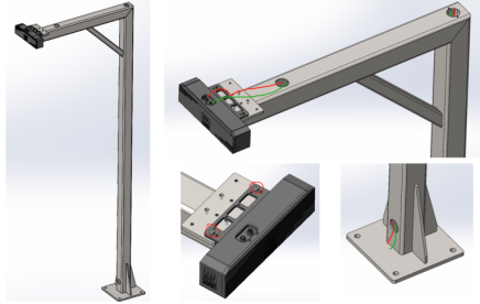
Design Requirements:
-
The specifications of the square steel should be no less than 100*100*5.
-
It is recommended to use integral welding.
-
The crossbar and column of the camera mounting frame should be equipped with necessary diagonal braces and ribs.
-
-
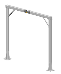
Portal Frame Design
This form is suitable for environments with noticeable vibrations. The portal frame provides a more robust support frame. Therefore, it can better resist external vibrations and impacts, and ensure the camera’s stability.
Sliding Camera Mounting Frame Designs
Feasible: Adjacent stacks share the same camera.
Based on different power components, sliding camera mounting frames can be divided into: servo module driven frames and pneumatic cylinder driven frames.
-
Servo Module Driven Frame
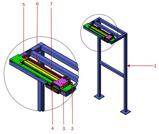
The servo module driven frame requires a smooth operation, with no impact on stopping and starting. Recommended normal operating speed: ≤250 mm/s. The components of a servo module driven frame are shown in the figure below: 1-frame body, 2-module mounting plate, 3-camera mounting plate, 4-camera, 5-servo module, 6-drag chain mounting plate, and 7-drag chain.
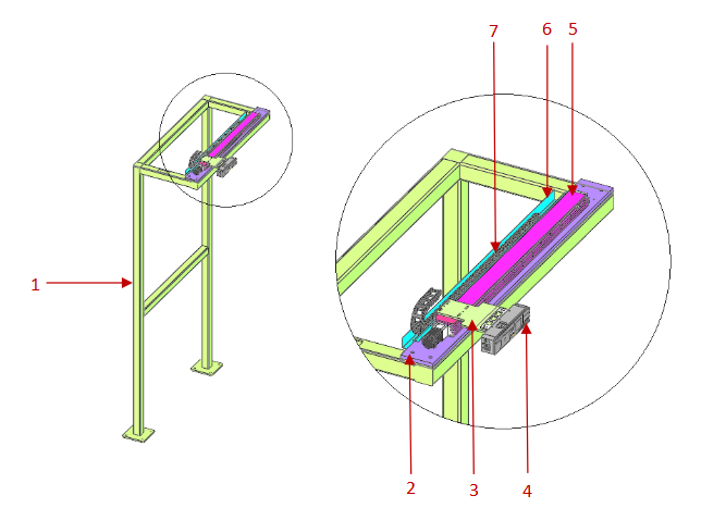
Frame body: Welded from 100*100 square steel. If the whole frame is high, you may add diagonal braces or use other securing methods. Module mounting plate and camera mounting frame: High strength and rigidity are required to ensure the stability of the camera when the servo module is in operation. Servo module: The repeat positioning precision of servo modules generally includes ±0.01 mm, ±0.02 mm, ±0.05 mm, ±0.1 mm, ±0.2 mm, etc. You can select the linear servo module according to the actual precision requirements of your project. It is recommended to use a servo motor for the driving part. Drag chain: Select standard market-available parts based on the diameter of your bus cable. Generally, the cross-sectional area occupied by the bus cable should be less than 60% to 80% of the internal volume of the drag chain. Drag chain mounting plate: Fabricated using sheet metal bending as required.
-
Pneumatic Cylinder Driven Frame (Not Recommended)
The positioning precision of pneumatic cylinders is slightly lower than that of servo modules., with a typical precision of ±0.1 mm. The pneumatic cylinder driven frame requires a smooth operation, with no impact on stopping and starting. Recommended normal operating speed: ≤200 mm/s. The components of a pneumatic cylinder driven frame are shown in the figure below: 1-frame body, 2-pneumatic cylinder mounting plate, 3-camera mounting plate, 4-camera, 5-pneumatic cylinder, 6-drag chain mounting plate, and 7-drag chain.
Pneumatic cylinder: Choose the cylinder stroke according to the actual distance of the on-site stacks. For the cylinder type, it is recommended to choose a guide rod cylinder. Otherwise it must be used with a linear guide. The pneumatic cylinder must be used with an oil buffer and a limit block. In addition, it should be equipped with an exhaust throttle valve. For how to design and select the frame body, pneumatic cylinder mounting plate, drag chain mounting plate and drag chain, please refer to the servo module driven frame.
Considering factors such as impacts on the pneumatic cylinder, overall operation precision, camera vibrations at the docking position, and long-term stability, this method is not recommended.
Vertical Camera Mounting Frame Designs
Feasible: Suitable for scenarios where the pallet pattern is tall, its length or width dimension is too large, and the point clouds of the sacks at the bottom have poor quality.
Based on different driving forces, vertical camera mounting frames can be divided into: pneumatic vertical camera mounting frames and electric vertical camera mounting frames.
-
Electric Vertical Camera Mounting Frame
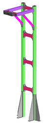
Design Requirements: The camera mounting frame should perform smoothly, with no severe impacts during operation; the movement speed should be less than 250 mm/s; ensure smooth and stable operation of the moving mechanism. The camera mounting frame should be rigid to ensure no vibrations while working. The components of an electric vertical camera mounting frame are shown in the figure below: 1-frame body, 2-3D camera, 3-camera mounting plate, 4-gear and rack assembly, 5-drag chain, and 6-drag chain mounting plate.
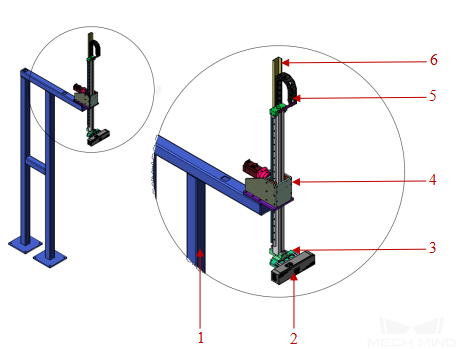
Gear and rack assembly: It is recommended to choose the brake motor to prevent the camera from falling in free fall after an unexpected power outage.
-
Pneumatic Vertical Camera Mounting Frame (Not Recommended)
Design Requirements: The camera mounting frame should perform smoothly, with no severe impacts during operation; the movement speed should be less than 200 mm/s; ensure smooth and stable operation of the moving mechanism.The camera mounting frame should be rigid to ensure no vibrations while working. The components of a pneumatic vertical camera mounting frame are shown in the figure below: 1-frame body, 2-camera mounting plate, 3-3D camera, 4-drag chain, 5-rodless cylinder, and 6-drag chain mounting plate.
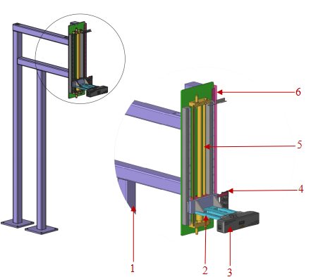
Pneumatic cylinder: Choose the cylinder stroke according to the actual distance of the on-site stacks. The pneumatic cylinder must be used with an oil buffer and a limit block. In addition, it should be equipped with an exhaust throttle valve. Choose the center-closed directional control valve for your pneumatic cylinder. This prevents the camera from falling in free fall after the air is shut off.
Considering factors such as impacts on the pneumatic cylinder, overall operation precision, camera vibrations at the docking position, and long-term stability, this method is not recommended.
Mounting Requirements for Mounting Frames in the ETH Setup
When mounting the frames in the ETH Setup, you should use chemical bolts or expansion bolts to secure the camera mounting frame to the ground. Those securing methods provide stable and reliable support and ensure that the camera does not shake.
For details about camera mounting requirements and guidelines for mounting camera cables, please refer to:
Mounting Frame Designs and Mounting Methods in the EIH Setup
The following section introduces two common design forms for mounting frames in the EIH Setup.
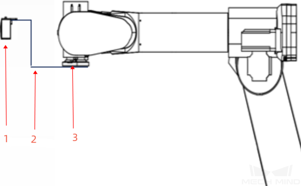
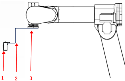
The camera is above the robot’s J6 axis flange
-
Advantage: When the robot’s arm span is small, this form helps raise the camera to expand the field of view.
-
Disadvantage: The rotation range of the robot’s J6 axis is limited and the mounting frame or the camera and the robot body may interfere with each other.
Structure diagram: 1-camera, 2-camera mounting frame, 3-robot’s J6 axis flange
The camera is below the robot’s J6 axis flange
-
Advantage: The robot’s J6 axis rotation is not affected by the camera or camera mounting frame.
-
Disadvantage: When the robot lifts to the same height, the image-capturing position is not high, resulting in a smaller field of view.
Structure diagram: 1-camera, 2-camera mounting frame, 3-robot’s J6 axis flange
Mounting Requirements for Mounting Frames in the EIH Setup
When mounting frames in the EIH Setup, you should take measures to prevent them from loosening, such as applying thread glue to the mounting bolts, using anti-loosening washers, etc.
For details about camera mounting requirements and guidelines for mounting camera cables, please refer to: