Waypoint Type
Waypoint Type Description
Tool |
The waypoint will be represented by the X, Y, Z values, Euler angles, quaternions or rotation vectors in the tool reference frame.
|
Joint positions (JPs) |
The waypoint will be represented by the joint positions of the robot.
|
Workobject pose |
The waypoint will be represented by the X, Y, Z values, Euler angles, quaternions or rotation vectors in the object reference frame. It focuses on describing the position and orientation of the actual workobjects that need to be operated or handled when the robot is performing tasks.
|
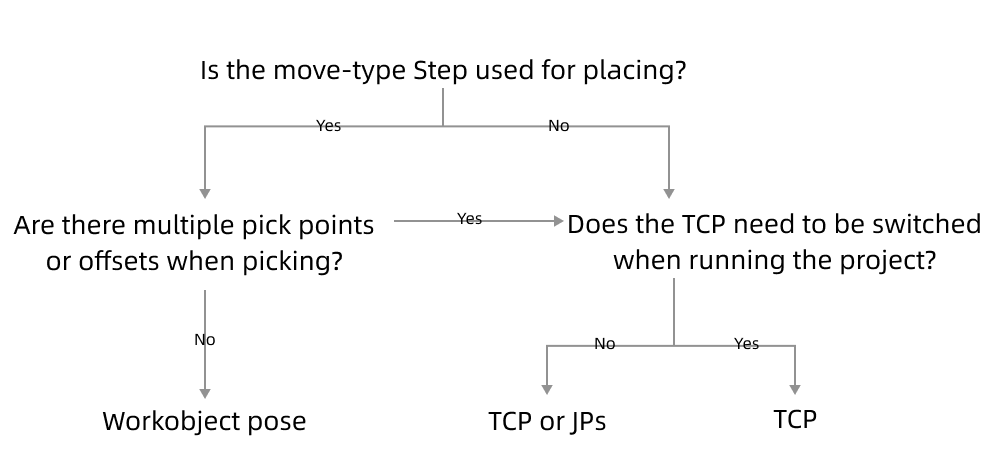
The method to determine the waypoint type is shown in the figure below.

Parameter Description
Edit pose |
Enter quaternions or Euler angles directly to adjust the pose. You can also copy and paste the pose. |
Transform pose |
Transform the current pose to a new one. It is suitable for fine-tuning. |
Rectify pose |
Set the coordinate of P1, P2, and P3 according to the instruction, and then rectify the object pose with the three-point method. It is suitable for scenarios where the objects are tilted and their poses cannot be easily determined. For instance, when a cuboid tilts, its pose is hard to determine. Rectify pose can be used here to calculate the pose of the cuboid and therefore the robot can move to the rectified pose. |
Edit JPs |
Similar to Edit Pose above; edit the JPs by copying and pasting or editing the JPs in either radians or degrees, which can be switched based on the actual requirement. |
|
Click to move the robot back to the specified waypoint. |
|
Get the pose of the simulated robot and set it as the waypoint. |
|
Show all the joint position solutions to the current waypoint. |