Project Construction Framework
In this section, a simple target object recognition project will be constructed as an example to show you the framework of project construction.
Understand Project Framework
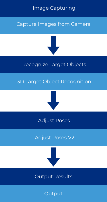
Target object recognition typically consists of four processes: capture images, recognize target objects, adjust poses, and output results. Each process corresponds to different Steps, which are:Capture Images from Camera, 3D Target Object Recognition, Adjust Poses V2, and Output.
Build the Project
Create and Save Solution
You can refer to Create and Save Solution.
Connect and Add Steps
After understanding the project framework and creating the solution, you can start to add and connect Steps and construct the project.
-
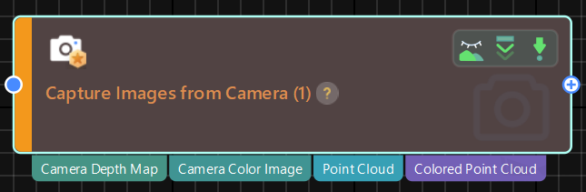
Add the “Capture Images from Camera” Step.
The Step can trigger the camera to capture images and acquire image data of the target object for subsequent target object recognition.
-
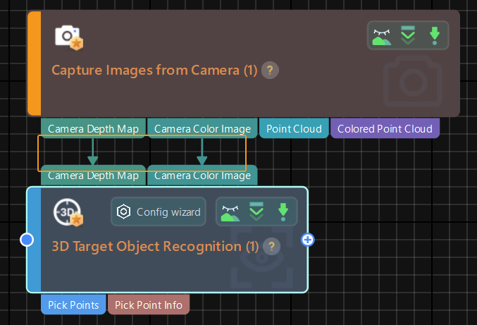
Add “3D Target Object Recognition” Step.
This Step is integrated with visual processing functions such as point cloud preprocessing, 3D matching, and removal of overlapped objects, facilitating a rapid recognition of target objects.
Place the Step below the “Capture Images from Camera” Step, and connect the ports of “Camera Depth Map” and “Camera Color Image” of the two Steps to each other. As shown below, now you have added the “3D Target Object Recognition” Step and input the data you need.
-
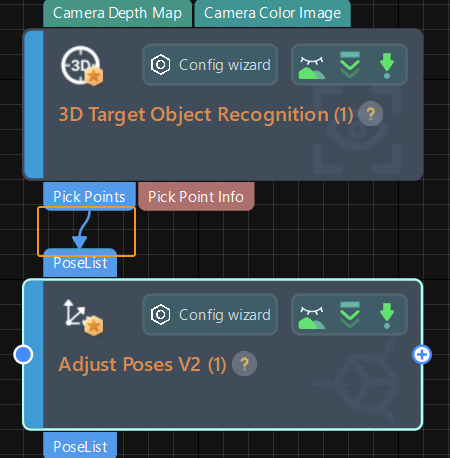
Add the “Adjust Poses V2” Step.
This Step allows you to manipulate poses input by the “3D Target Object Recognition” Step, including transforming them into the robot reference frame, as well as performing translation, rotation, and sorting operations.
Place the Step below the “3D Target Object Recognition” Step and connect the “Pick Points” ports of the two Steps to each other.
-
Add the “Output” Step.
This Step can send the vision results of the current project to Mech-Viz or communication components for subsequent picking tasks.
Since the “Output” Step shows ports related to path planning by default and this project requires outputting data related to picking points of the target object, you need to adjust the Step’s Port Type to Predefined (vision result) in the Step Parameters panel.
After adjusting the step parameter, place the “Output” Step below the “Adjust Poses V2” Step and connect the “Pick Points” ports of the two Steps to each other. Besides, connect the “Pick Point Info” output port of the “3D Target Object Recognition” Step and the “Colored Point Cloud” output port of the “Capture Images from Camera” Step to the “Output” Step respectively.
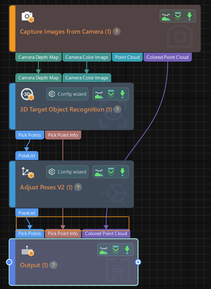
Till now, you have constructed a simple target object recognition project. You can use the shortcut Ctrl + S or go to in the menu bar to save the project.
|
After adding and connecting all the Steps, you can arrange the layout of the Steps to make the logic of the data flow clearer. There are three ways to arrange the layout of the Steps:
|
After the construction of the project is completed, you can start to run and debug the project.