Collision Model Configuration
You can adjust the dimensions of the collision model during the project construction phase to make the collision detection more accurate and efficient.
Scene Model
Adding a scene object model can represent the scene in the software, which facilitates calculating the collision-free robot motion path.
Scene models should meet the following requirements:
-
Complete: Add scene models of all objects within the reach of the robot as completely as possible to avoid potential collision risk.
-
Accuracy: Inaccurate poses or dimensions of the scene model may lead to over-detection of collisions or missed detection.
-
Allow safety margin: To ensure the safe operation of the robot, you can increase the size of relevant object models when necessary to provide a sufficient safety margin. For locations with high requirements for collision detection accuracy (such as near the pick point), the scene model should closely match the actual dimensions to prevent calculation failures due to enlarged dimensions. For locations with low requirements for collision detection accuracy but high requirements for operational safety (such as camera models in the ETH scenario), the scene model should include a large enough safety margin.
-
Model simplification: If the scene model contains too much detail, it will not improve the accuracy of collision detection and will significantly increase the calculation time.
The recommended methods to build a scene model are as follows:
-
To improve the efficiency of collision detection, it is recommended to create a cuboid or cylinder-shaped model to cover the custom model in the 3D simulation area (as shown below).
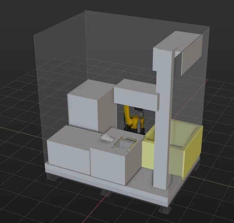
-
If the actual scenario does not contain a safety fence, you can create a simulated wall using the cuboid scene object. When collision detection is enabled, this will effectively prevent the robot from moving beyond the workstation.
-
It is recommended to manually operate the robot to approach the objects in the workstation and synchronize the robot’s poses in the Mech-Viz software. This allows you to check whether the robot will collide with the created scene models.
-
When creating a scene object, it is recommended to include a safety margin of at least 5 mm to ensure safety.
-
If a scene object of the cuboid, bin, or cylinder type coincides with the custom model, open the Scene Object Configuration window and clear the Involve in collision detection checkbox to stop the collision detection with the custom model. Only scene objects of the cuboid, bin, or cylinder type will be involved in collision detection.
| For stations that have undergone camera extrinsic parameter calibration, you can capture an image to check if the point cloud coincides with the model to ensure its accuracy. |
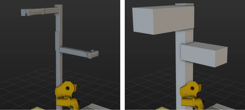
Camera Model
When building a scene model, it is recommended to put a cuboid-type scene object at the mounting position of the real camera, to avoid collisions between the robot and the real camera.
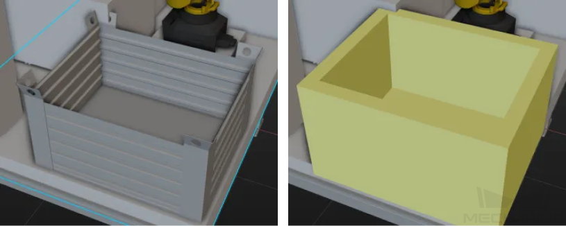
Bin Model
You can create a scene model of the Bin type in Mech-Viz or import a scene model of the Custom model type for collision detection. Below are the advantages and disadvantages of the two methods:
-
Create a bin-type scene model
-
Advantage: The model size can be adjusted manually, allowing for stricter collision detection settings. It is recommended to increase the thickness of the cuboid bin by 5 mm.
-
Disadvantage: The real bin, which is usually not a standard cuboid, may be different from the created model bin. If the bin model is larger than the actual bin, target objects near the bin walls may become embedded in the bin model, reducing the bin clearance rate. If the actual bin is larger than the bin model, the bin walls may be scratched during actual picking.
-
-
Import a custom bin model
-
Advantage: The custom model closely matches the actual bin’s shape, preventing false detections near the bin walls when picking the target objects. Recommended for special-shaped bin scenarios.
-
Disadvantage: Machining errors or deformation may cause differences between the real bin and imported custom model, leading to over-detection of collisions or missed detection.
-
When the poses of the incoming bins vary on site, you need to determine the actual bin poses using vision recognition and adjust the poses of the bin models in the 3D simulation area accordingly to ensure reliable collision detection. For more instructions, refer to Update Bin Pose in Mech-Viz.
Tool Model
In 2.0.0, collision models for tools are supported in both OBJ and STL formats. It is recommended to use the OBJ format collision model first.
As the STL model is hollow, the system can only detect the collision between its outer surface and the point cloud during point cloud collision detection, and therefore it is difficult to accurately assess the severity of the collision. In addition, it is challenging to set a stable collision threshold for STL models. In contrast, the OBJ model is solid and more suitable for collision detection of end tools.
If you need to use the tool model in STL format, it is recommended to set the point cloud form for collision detection to Point cloud column for the target object and scene object. In this case, the collision models of the target object and scene object can be considered solid, reducing the chance of missed detection.
Create the Tool Model in OBJ Format
You can use the Model Editor to create convex hulls based on STL or STEP models and convert them to the OBJ format. To save time when creating a collision model for the end tool, it’s not always necessary to replicate every detail of the original model in the convex hulls. You can omit certain details based on the specific requirements, as illustrated below.
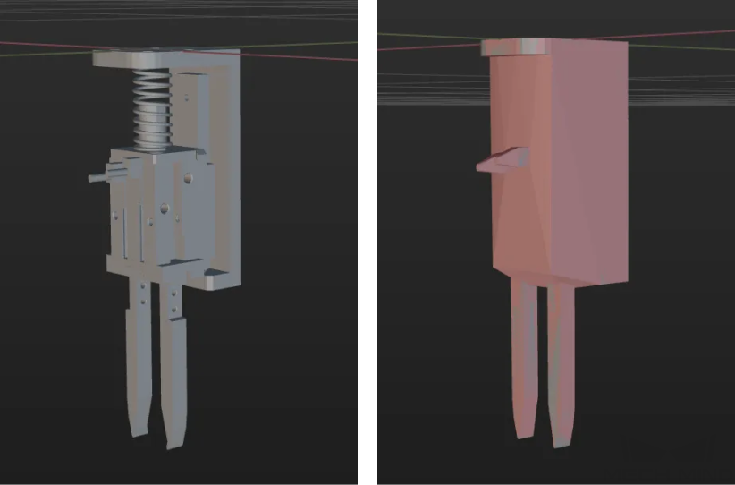
Simplified Approach
-
The gripper fingers should be modeled with as much detail as possible to accurately represent their physical form, ensuring the accuracy of collision detection and the success rate of path planning.
-
For mechanical structures that are farther away from the gripper fingers, the design can be simplified by using cuboid convex hulls instead of complex structural designs to improve efficiency.
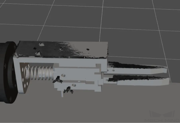
Tool Model Check
For stations that have undergone camera extrinsic parameter calibration, you can capture an image and check if the tool point cloud coincides with the model.