Robot Communication Configuration
In this tutorial, you will learn how to load the Standard Interface program files to the Yaskawa robot, and set up the Standard Interface communication between the Mech-Mind Vision System and the robot.
|
Preparation before Loading
Check Controller and Software Compatibility
-
Confirm that the robot is a 6-axis YASKAWA robot. In this guide, YASKAWA_GP8 is used.
-
Confirm that the robot controller model and the system version meet the requirements below.
Controller model System version DX200
DN3.16.00A-00
YRC1000
YAS2.94.00-00
YRC1000micro
YBS2.31.00-00
In this guide, the robot YRC1000 (YAS2.94.00-00) is used. -
Confirm that the Ethernet option has been enabled for the YASKAWA robot.
Click here for instructions
-
Press and hold the MAIN MENU key on the teach pendant, and power on the robot to enter the maintenance mode.
If the robot is already started, please restart the robot while pressing the MAIN MENU key on the teach pendant. 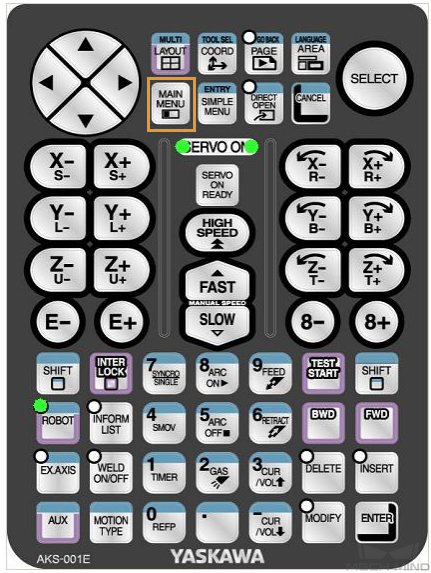
-
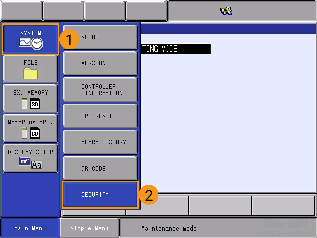
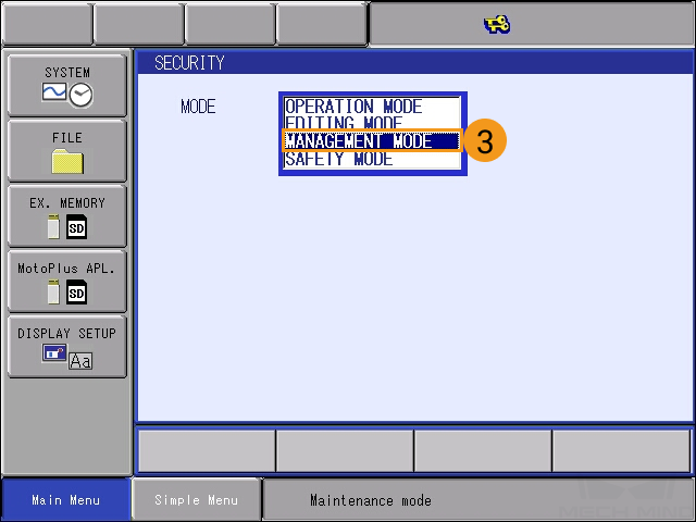
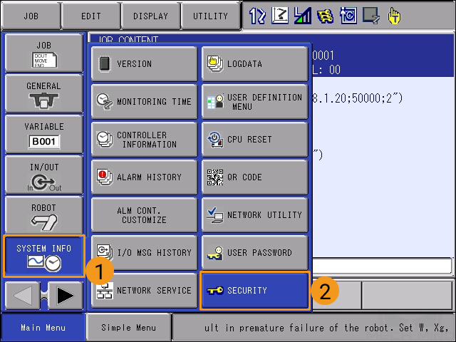
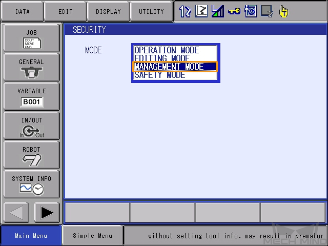
In the maintenance mode, select .
-
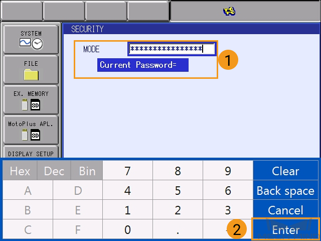
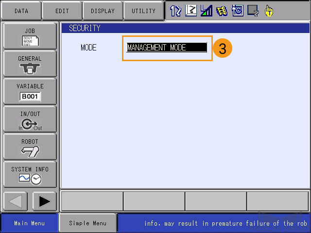
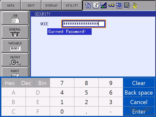
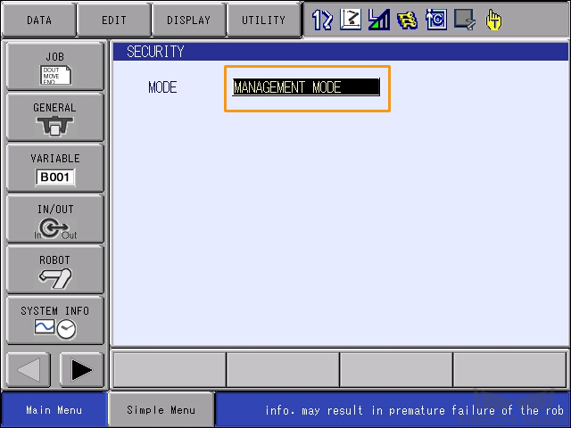
Enter the password (which is sixteen 9s by default), and then select Enter to enter the MANAGEMENT MODE.
-
In Main Menu, select .
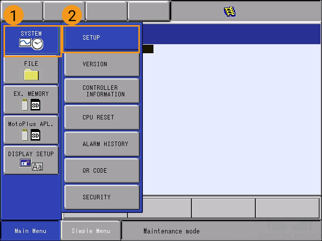
-
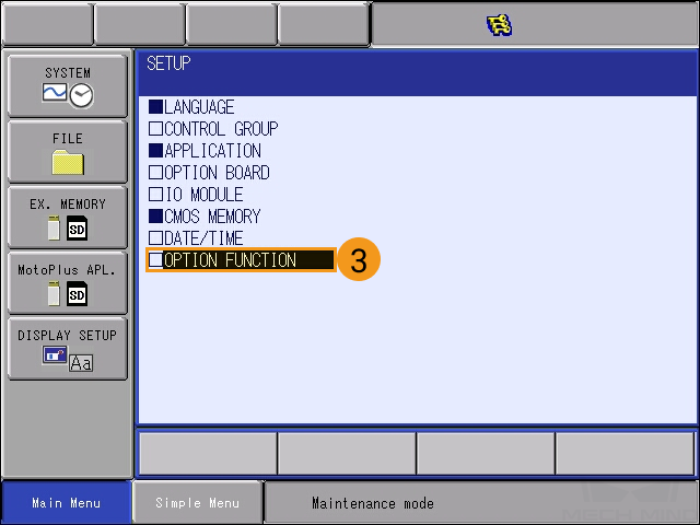
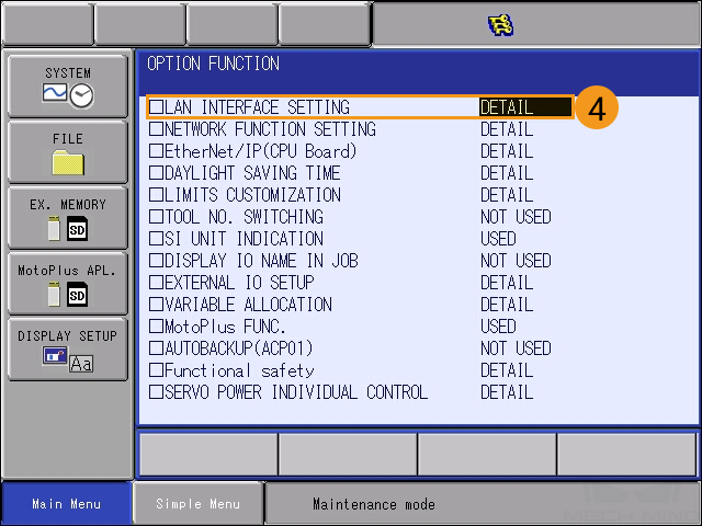
In the OPTION FUNCTION interface, select DETAIL of NETWORK FUNCTION SETTING, and then press SELECT on the teach pendant to enter the NETWORK FUNCTION SETTING interface.
-
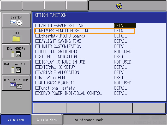
Check whether the status of ETHERNET is displayed as USED.
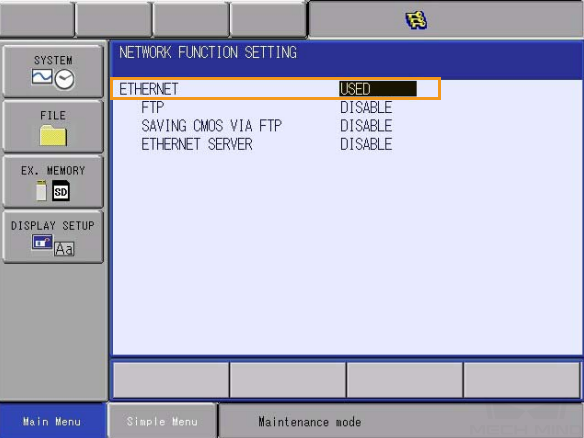
If the status is NOT USED, please contact the robot manufacturer for support.
-
-
Confirm that the MotoPlus option has been enabled for the YASKAWA robot.
Click here for instructions
-
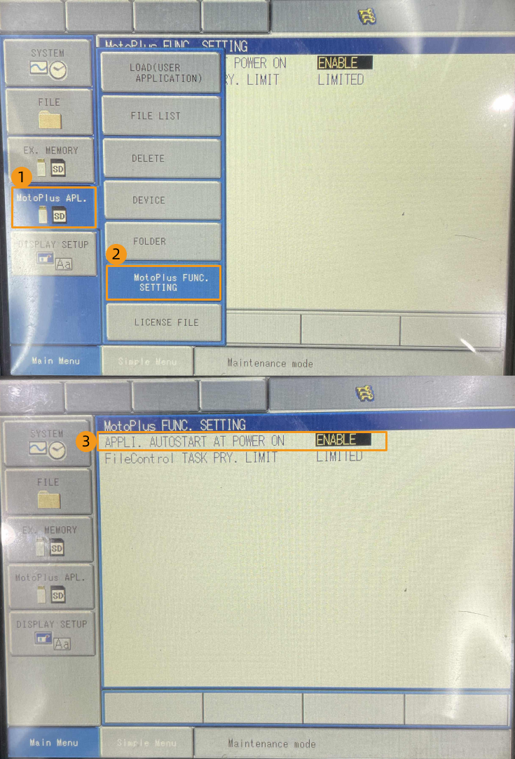
In the MANAGEMENT MODE of the maintenance mode, select on the Main Menu.
-
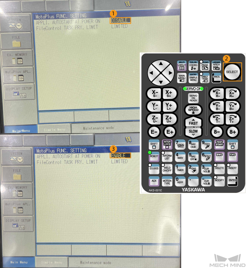
On the MotoPlus FUNC. SETTING interface, check whether the status of APPLI. AUTOSTART AT POWER ON is ENABLE.
-
If the status is DISABLE, select DISABLE, and press SELECT on the teach pendant to switch the status to ENABLE.
-
|
If the preceding conditions cannot be met, the vision system cannot communicate with the robot through the Standard Interface. Please contact the robot manufacturer for support. |
Set up Network Connection
-
If you are using the YRC1000 controller, plug the Ethernet cable of the IPC into the LAN2 (CN106) port on the CPU board of the robot controller.
-
If you are using the DX200 controller, plug the Ethernet cable of the IPC into the CN104 port on the CPU board of the robot controller.
-
For the YRC1000 controller:
-
The LAN1 port is only used to connect the teach pendant and cannot be used to connect the IPC Ethernet cable.
-
If the LAN2 port is occupied, use LAN3 instead, to connect the IPC Ethernet cable.
-
-
-
Make sure that the IP address of the YASKAWA robot and that of the IPC are in the same subnet.
Click here for instructions
-
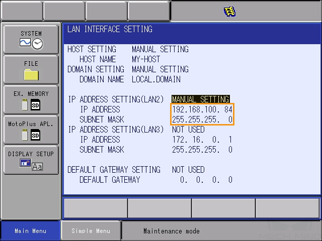
At the MANAGEMENT MODE of the maintenance mode, select on the Main Menu. In the OPTION FUNCTION interface, select LAN INTERFACE SETTING.
-
Check the IP address of the robot (i.e., the IP address of LAN2).
-
Make sure that the IP address of the robot and that of the IPC are in the same subnet. If they are not in the same subnet, please refer to the section Set the IP Addresses on the IPC to modify the IP address of the IPC.
-
Create a Mech-Vision Project and Save It
-
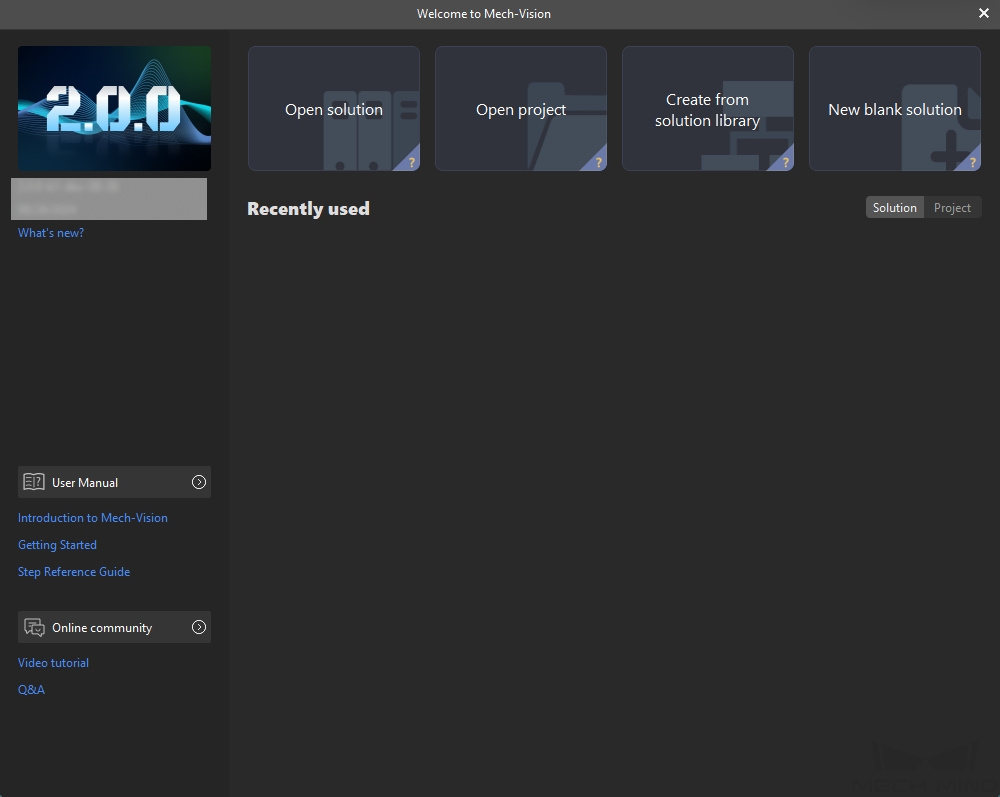
Open Mech-Vision. If the Welcome interface as shown below is displayed, it indicates that Mech-Vision is started successfully.
-
In the Welcome interface of Mech-Vision, click Create from solution library to open the Solution Library.

The Solution Library is a resource library that provides typical solutions or projects (with sample data) from various application scenarios. -
In the Application Template tab of the Solution Library, select the High-Precision Positioning and Assembly solution, as shown below.
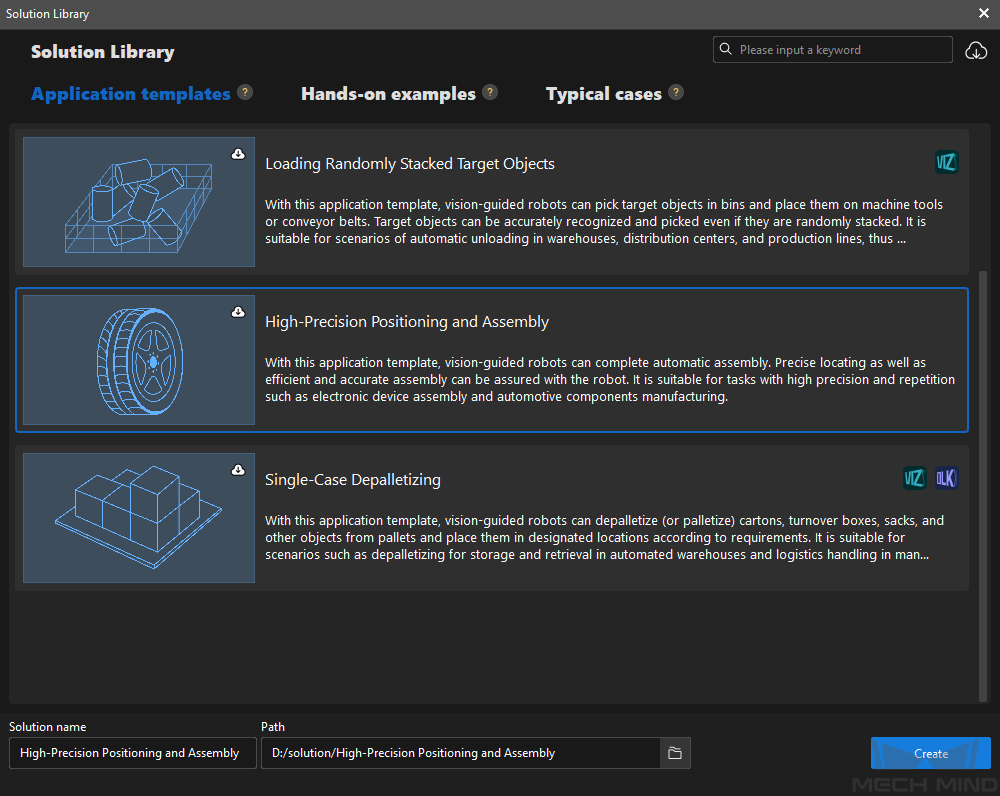
If you cannot find the High-Precision Positioning and Assembly solution in the Solution Library, click the Download icon in the upper-right corner.
-
Set the solution name and path, and then click Create.
After the project is created, the created solution and project will be displayed in the project list in the upper-left corner of the Mech-Vision main interface.
-
A solution is a set of configurations and data related to robots and robot communication, vision processing, path planning, etc. that are required for the machine vision application.
-
A project is a workflow of vision processing in the solution. Normally, a solution only contains one Mech-Vision project, but it may contain more than one project in complex application scenarios.
-
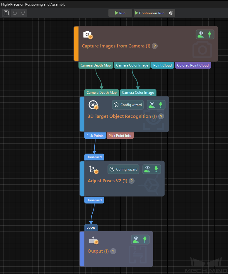
The High-Precision Positioning and Assembly solution only contains one project “High-Precision Positioning and Assembly”.
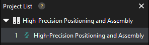
In the Graphical Programming Workspace of the main interface, the workflow of the “High-Precision Positioning and Assembly” project will be displayed.
-
-
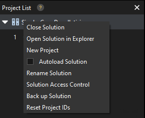
In the project list, right-click the solution, and select Autoload Solution.
After this solution is set to autoload, the project name will be displayed in green, and the project ID will be displayed in the left of the project name.
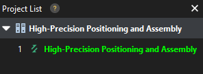
The project ID will be used by the robot pick-and-place program to trigger the Mech-Vision project to run. -
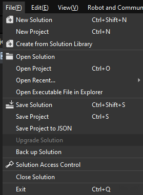
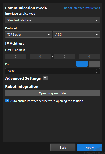
On the menu bar, select .
Set up Robot Communication Configuration
In this example, the robot communication configuration has been set for the YASKAWA robot (YASKAWA_GP8) by default. The Robot Communication Configuration option on the toolbar is enabled.
Prepare Program Files
-
On the IPC, go to
Communication Component/Robot_Interface/YASKAWAin the installation directory of Mech-Vision & Mech-Viz. -
If you are using the YRC1000 controller, copy the JBI folder and the mm_module_yrc1000.out file to the root directory of the empty USB flash drive which is formatted already.
-
Please ensure that your flash drive is formatted in advance and the file system of the flash drive is FAT32.
-
If you are using the DX200 controller, you need to copy the backend program file mm_module_dx200.out in this step.
-
mm_module_yrc1000.out: the robot backend program file (MotoPlus application file).
-
JBI : the folder storing robot frontend program files (Job files).
-
-
Plug the USB flash drive into the USB port on the rear panel of the teach pendant.
Make Sure That No Program Is Running in MotoPlus
Before you load the robot program files to the robot, make sure that no other MotoPlus programs are running.
-
If no programs are running, skip this section.
-
If there are any running program, delete those application programs.
Click here for instructions
-
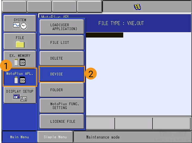
In the MANAGEMENT MODE of the maintenance mode, select on the Main Menu.
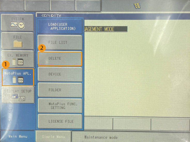
-
On the MotoPlus APL. DELETE interface, select the program file to be deleted, and then press SELECT on the teach pendant to select this file.
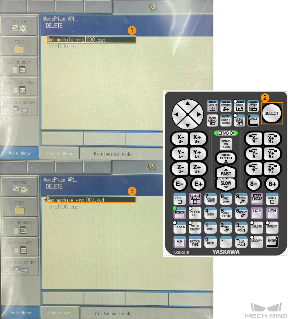
-
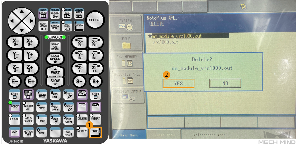
Press ENTER on the teach pendant, and press the YES button on the pop-up dialog box to delete the program.
-
Load the Program Files
Load the Backend Program File to the Robot
-
Press and hold the MAIN MENU key on the teach pendant, and power on the robot to enter the maintenance mode.
If the robot is already started, please restart the robot while pressing the MAIN MENU key on the teach pendant. -
In the maintenance mode, select .
-
Enter the password (which is sixteen 9s by default), and then select Enter to enter the MANAGEMENT MODE.
-
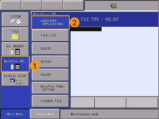
Select on the Main Menu.
-
Select .
-
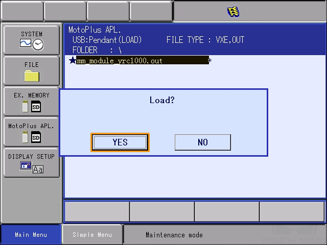
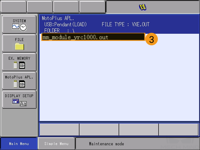
Select mm_module_yrc1000.out. Press ENTER on the teach pendant and then select YES to start loading.
If you are using the DX200 controller , you need to select mm_module_dx200.out in this step. 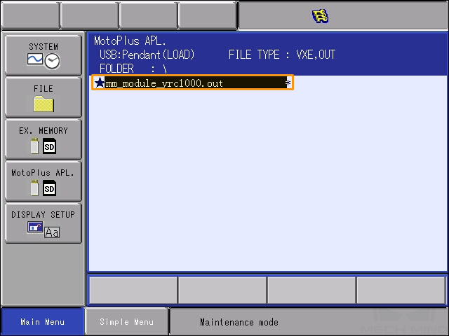
-
After the loading completes, select . If you can see the backend program file (mm_module_yrc1000.out), the loading of the backend program file is successful.
If you are using the DX200 controller , you will see mm_module_dx200.out here after the loading succeeds. 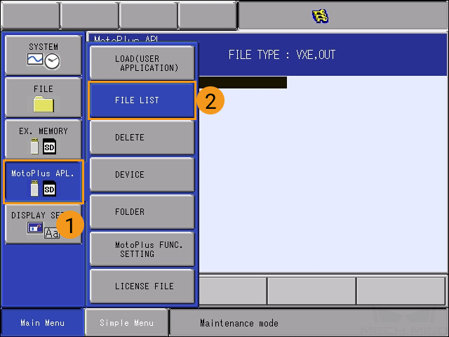
-
After you have loaded the backend program file, reboot the robot to enter the online mode.
You need to load the frontend program files and the example program files under the online mode. Therefore, you need to perform this operation after loading the backend program file.
Load the Frontend Program Files to the Robot
-
Under the online mode, select on Main Menu of the teach pendant.
-
Select MANAGEMENT MODE in the drop-down menu.
-
Enter the default password, which is sixteen 9s.
Select ENTER in the lower-right corner of the teach pendant screen to enter the management mode.
-
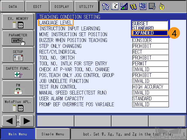
Select the right-arrow
 button in the lower-left corner of the teach pendant screen. Then, select , and select EXPANDED in the drop-down menu of LANGUAGE LEVEL.
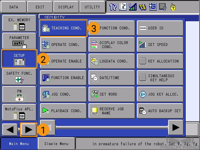
-
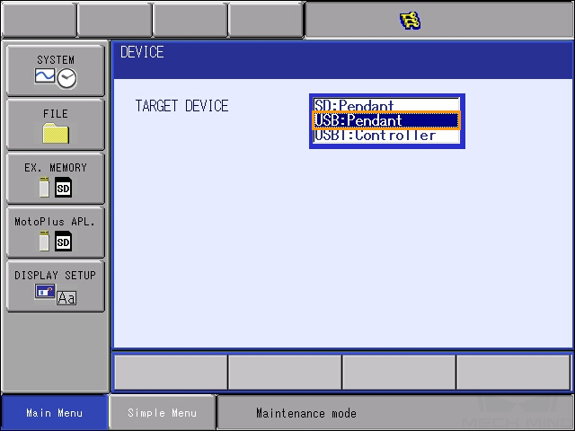
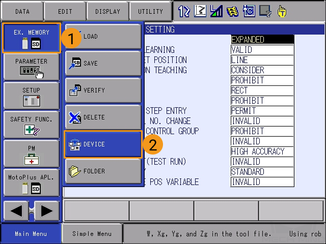
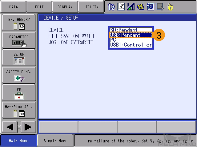
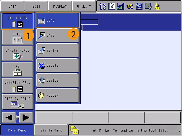
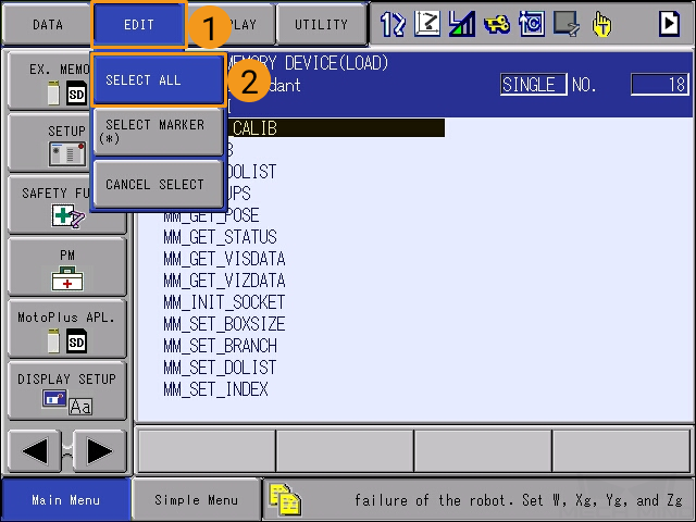
Select , and then select USB:Pendant for DEVICE.
-
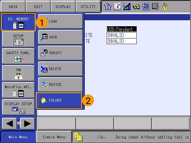
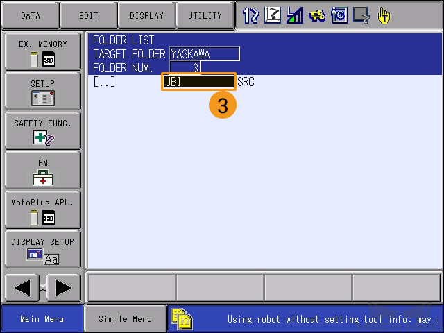
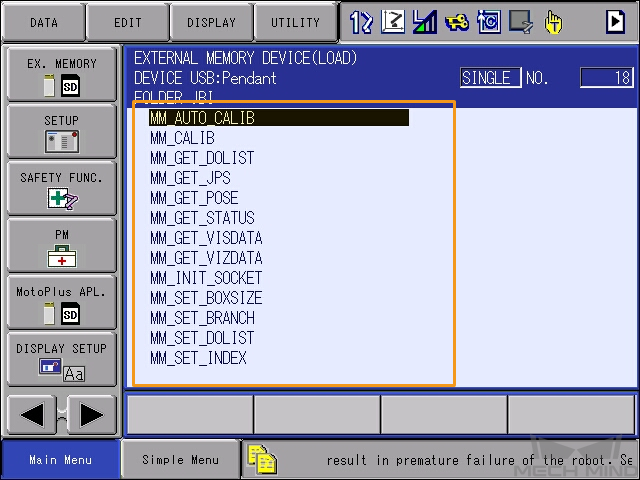
Select . In the FOLDER LIST, select and enter the JBI folder.
-
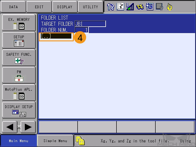
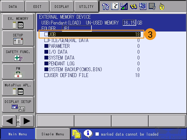
Select . Select JOB, and the programs to be loaded will be displayed.

-
Select .
-
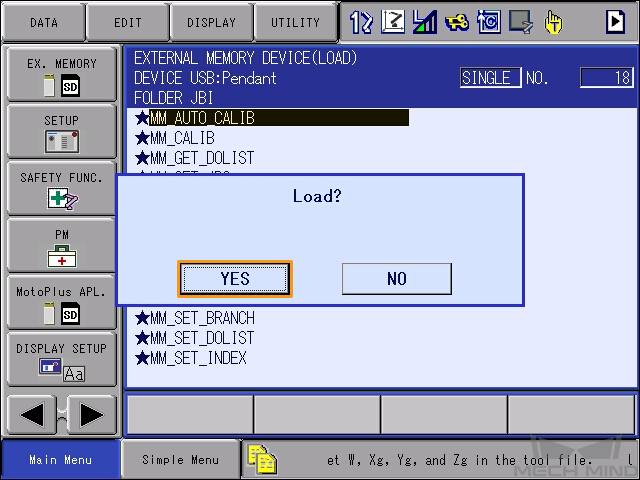
Press ENTER on the teach pendant. Select YES in the pop-up message to start loading the frontend programs.
-
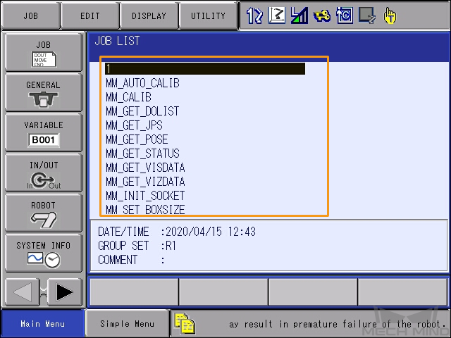
After loading the frontend programs, select to view the list of loaded programs. If you can see all frontend programs in the JOB LIST, the loading of is successful.
Test Standard Interface Communication
-
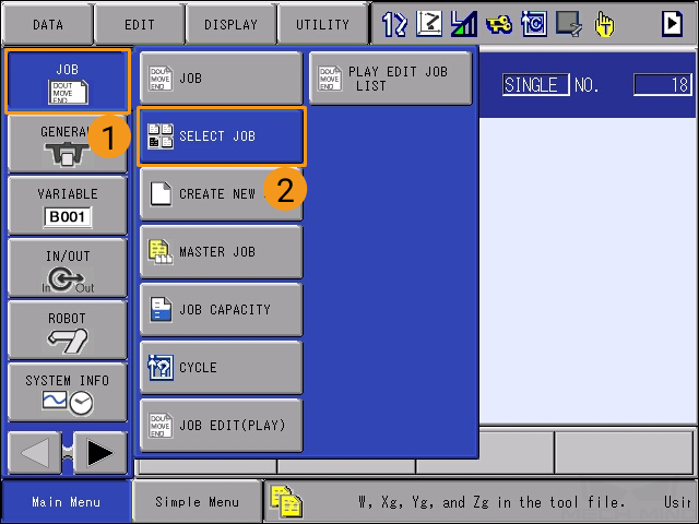
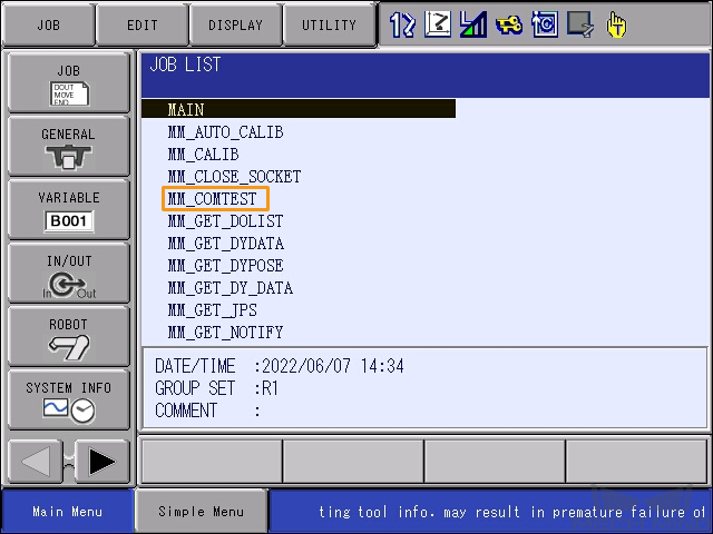
On the teach pendant, select on the Main Menu to enter the JOB LIST interface.
-
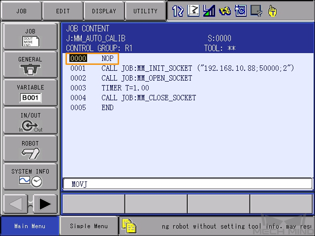
Select the MM_COMTEST program, and press SELECT to open the program.
-
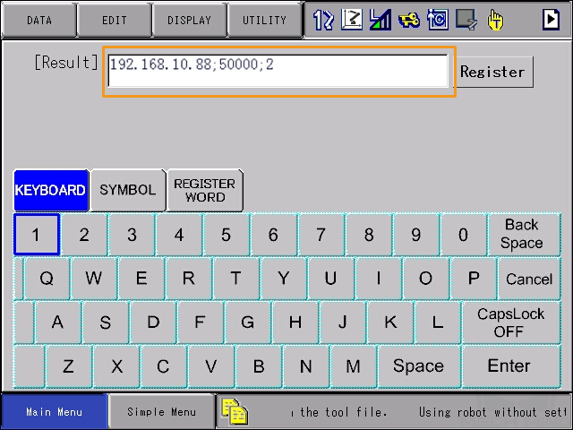
Select the content of line 0001, and then select the IP address and port number in the textbox at the bottom. Press ENTER to enter the edit interface.
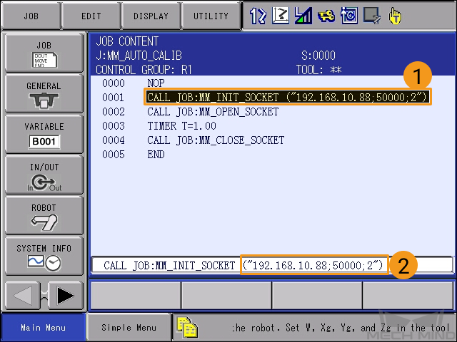
-
Change the IP address to that of the IPC. If the host port number set in Mech-Vision is modified, the port number 50000 here should be modified accordingly to make it consistent with the host port number set in Mech-Vision.
-
Turn the key of the teach pendant to the TEACH mode.
-
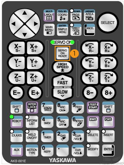
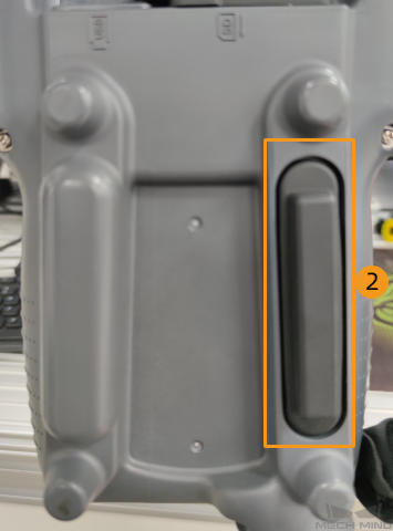
In the TEACH mode, press SERVO ON READY on the teach pendant, and then hold the deadman switch on the back while moving the cursor back to line 0000.
This step ensures that the job runs from the first line.
-
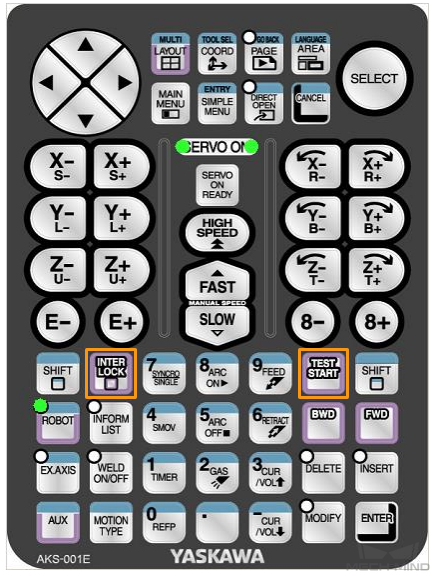
Press INTER LOCK and TEST START together on the teach pendant.
This step is a communication test.
-
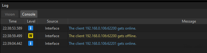
If the communication between the robot and the vision system is set up, a log will be recorded on the Console tab of the Log panel of Mech-Vision.
Now you have loaded the robot Standard Interface program and the configuration files to the robot system to establish the Standard Interface communication between the vision system and the robot.