Adjust Poses (Point to Reference Point)
This tutorial first introduces the application scenarios and examples of pointing poses towards the reference point. Then it uses the example project “Adjust Poses (Point to Reference Point)” as an application guide, illustrating how to adjust the parameters in the Adjust Poses V2 Step. It also provides notes for real applications.
Application Scenarios
Pointing the pose towards the reference point is suitable for shaft loading scenarios. When picking objects near the bin walls, the gripper will collide with the bin and therefore needs to be tilted for picking.
Application Examples
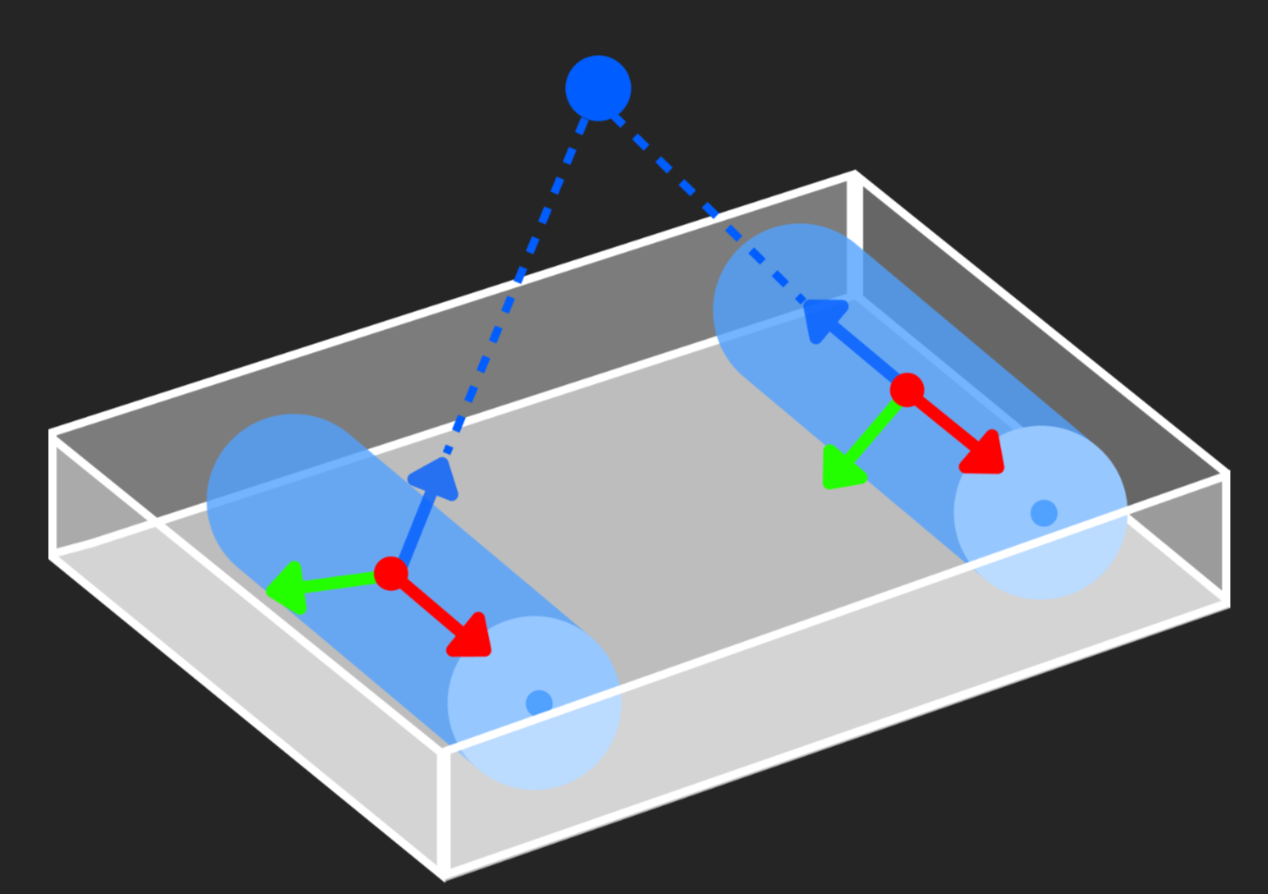
Pointing poses towards the reference point is suitable for shaft loading scenarios. When picking objects near the bin sidewalls, the gripper is likely to collide with the bin. Therefore, it is necessary to make the Z-axes of the shaft poses point to a specific point (i.e., the reference point), sort the shafts according to their distances to the reference pose, and then pick them in sequence.
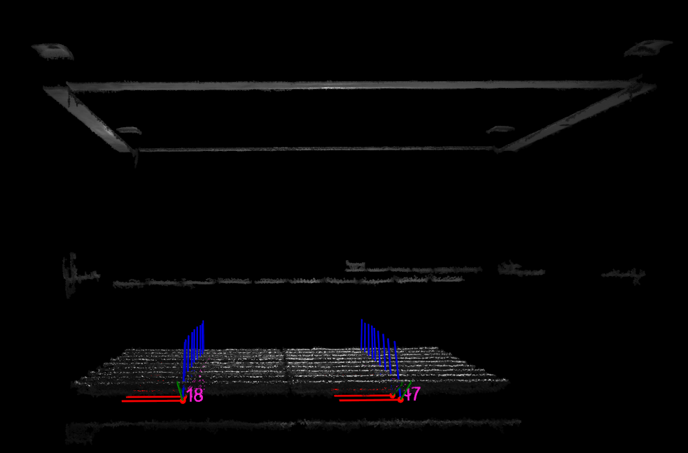
After poses are pointed towards the reference point, the robot picking effect is shown below.
The following sections introduce the application guidance and notes based on this example.
Application Guide
After understanding the application scenarios of pointing poses towards the reference point, you can go to the Solution Library to download the relevant project and learn how to adjust parameters according to the following content.
The “Adjust Poses (Point to Reference Point)” project is located in the Mech-Vision Solution Library. You can go to the hands-on examples category to obtain the resources and create the project. After creating the project, click the Adjust Poses V2 Step, and then click the Config wizard button to open the pose adjustment tool and adjust parameters. This configuration consists of three workflows: pose adjustment, processing rules, and general settings.

-
Pose adjustment: Adjusts the pose orientations.
-
Processing rules: Sorts poses according to the actual requirement and filters out ineligible poses.
-
General settings: Provides settings other than pose processing. Currently, this step only supports sorting other data (such as the carton dimensions) together with the corresponding poses.
The following section introduces the key parameters to be adjusted in each workflow.
Pose adjustment
-
Select the method of adjusting the orientation.
To make the object poses point to the reference point uniformly, set Orientation to Point to reference point.
-
Set the reference pose.
To adjust the pose orientation, you need to set the reference pose. For detailed instructions on setting the reference pose, refer to Set Reference Pose. In this example project, you need to set the parameter value to Drag with pose manipulator.
-
Set the pointing axis and the axis to be fixed.
In this tutorial, you need to set the Pointing axis to Z-axis and the Axis to be fixed to X-axis. In real scenarios, set the Pointing axis and Axis to be fixed according to the symmetry of the target objects.
-
Set the rotation angle increment.
To ensure picking accuracy, utilize object symmetry, and reduce errors, you can adjust the value of the Rotation angle increment. In the shaft loading scenario, the shaft pose should point to the reference point as much as possible. Therefore, you need to adjust the value of this parameter.
After configuring the pose adjustment workflow, click the Next button to enter the processing rules page.
Processing rules
-
Select the sorting type.
In the cylindrical shaft loading scenario, it is recommended to set the Sorting type to Sort by distance from pose to reference pose. This sorting type calculates distances from all poses to be sorted to the reference pose and sorts the poses according to their distances.
-
Set the reference pose.
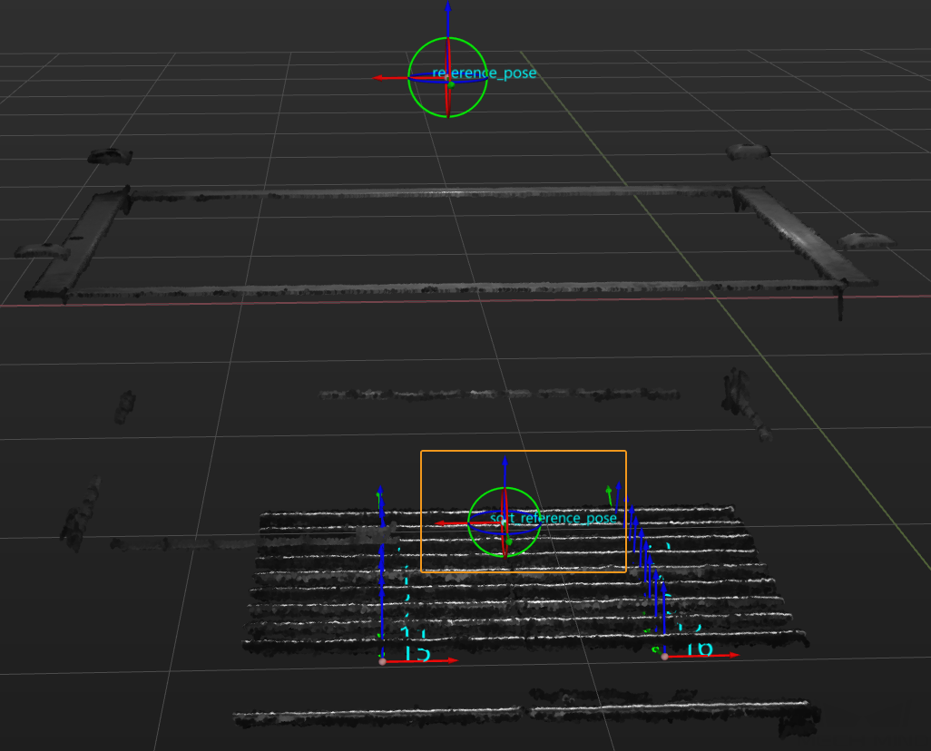
To determine the picking start point, you need to set the reference pose. For detailed instructions on setting the reference pose, refer to Set Reference Pose. In the shaft loading scenario in this example project, the bin position is fixed. Therefore, you can select Drag with pose manipulator to set the reference pose.
-
Set the sorting order.
Set the Order to Ascending, i.e., arranging the target objects by the distances of their poses to the reference pose from the shortest to longest, making the subsequent picking easier.
After configuring the processing rules, click the Next button to open the general settings page.
Notes
In actual applications, please understand and follow the following precautions, then add the Adjust Poses V2 Step to your project, and connect the data streams to quickly sort poses by their distances to the reference pose from smallest to largest.
-
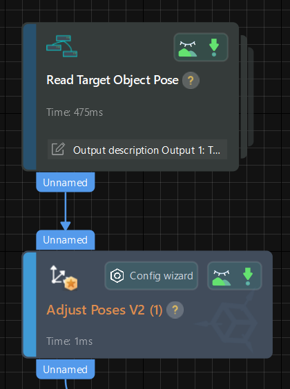
The Adjust Poses V2 Step should be preceded by a Step or Procedure, such as the Read Target Object Pose Procedure, that recognizes and outputs the target object center poses. The pose output port of this Step or Procedure connects the pose input port of the Adjust Poses V2 Step for pose sorting.
-
The Adjust Poses V2 Step should be followed by a Step with a pose input port, such as the Path Planning and Output Steps, to output the adjusted pose, so that the robot can pick the shafts by their distances to the reference pose.