Hand-Eye Calibration
In this tutorial, you will perform the automatic hand-eye calibration in the eye-to-hand setup.
|
The hand-eye calibration establishes the transformation relationship between the camera and robot reference frames (that is camera extrinsic parameters). With this relationship, the object pose determined by the vision system can be transformed into that in the robot reference frame, which guides the robot in performing its tasks. |
Preparation before Calibration
Before hand-eye calibration, you need to finish the following preparations:
-
Construct the Mech-Mind Vision System (completed).
-
Complete robot communication configuration (completed).
Prepare the Materials Required for Calibration
The automatic hand-eye calibration in the ETH setup needs to use the calibration board.
Please prepare the calibration board according to the following requirements:
-
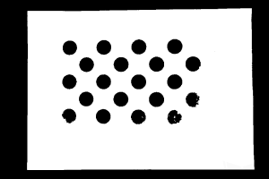
Ensure that the circles of the calibration board are clearly visible and without obvious scratches, and the board does not suffer from deformations.
-
In the ETH setup, mount the robot-specific bracket for calibration board onto the robot flange, and then mount the calibration board onto the bracket. Ensure that the calibration board is securely mounted, located at the center of the camera’s field of view, and as parallel to the plane of the camera as possible, even if the calibration board is as perpendicular to the Z-axis of the camera reference frame as possible.
If an undetachable gripper is connected to the robot flange, you can attach the calibration board directly to the gripper.
Check the Point Cloud Quality of the Calibration Board
| The point cloud quality of the calibration board will affect the accuracy of hand-eye calibration. Check the point cloud quality of the calibration board to ensure the accuracy and reliability of the calibration results. The calibration process includes the step of checking the point cloud quality of the calibration board. You can also check the point cloud quality of the calibration board before starting the calibration to save time. |
-
Place the calibration board horizontally at the center of the working plane within the camera’s field of view.
-
Open the Mech-Eye Viewer software, select the camera used by the project, and then select the “calib” parameter group and adjust camera parameters.
-
Adjust the 2D parameters to ensure that the overall 2D image is not too dark, and each calibration circle is clearly visible.
-
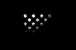
Adjust the 3D parameters to ensure that each calibration circle on the calibration board is complete and visible.
If the on-site ambient lights are not ideal and affect the quality of 2D images and point clouds, you can use shading or supplemental light to improve the lighting conditions.
-
Make sure that the point cloud quality of the calibration board is up to standard after completing the preceding steps.
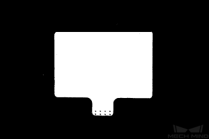
Normal Overexposed Underexposed 2D image
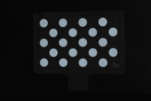
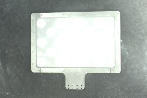
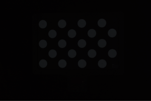
Point cloud
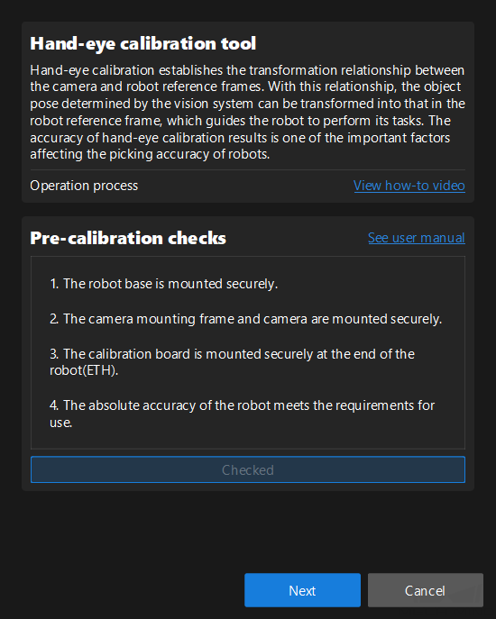
Complete Pre-calibration Checks
Before calibration, confirm that the following checks have been completed:
Pre-calibration Configuration
-
Open Mech-Vision, and click the Camera Calibration button in the toolbar. The Configuration before Calibration window will be prompted.
-
After confirming that pre-calibration checks are completed, click I’ve finished all checks, and then click Next.
-
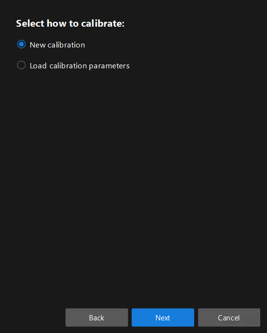
In the Select how to calibrate window, select the New calibration radio button, and then click the Next button.
-
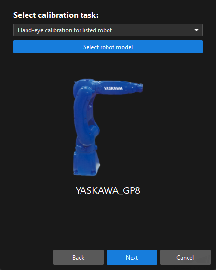
In the Select calibration task window, confirm that the robot model is “YASKAWA_GP8”, and then click the Next button.
-
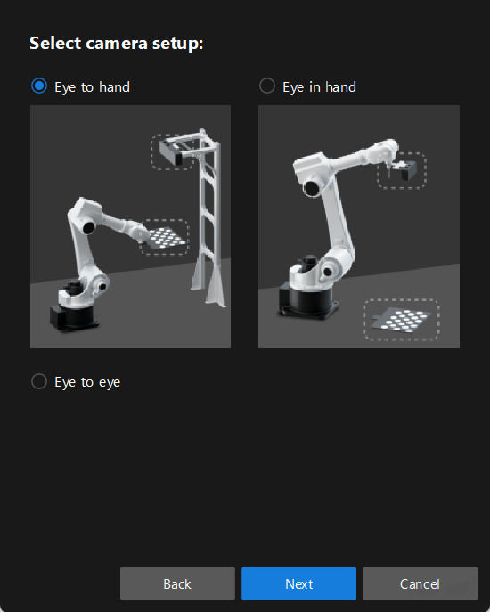
In the Select camera setup window, select the Eye to hand radio button, and then click the Next button.
-
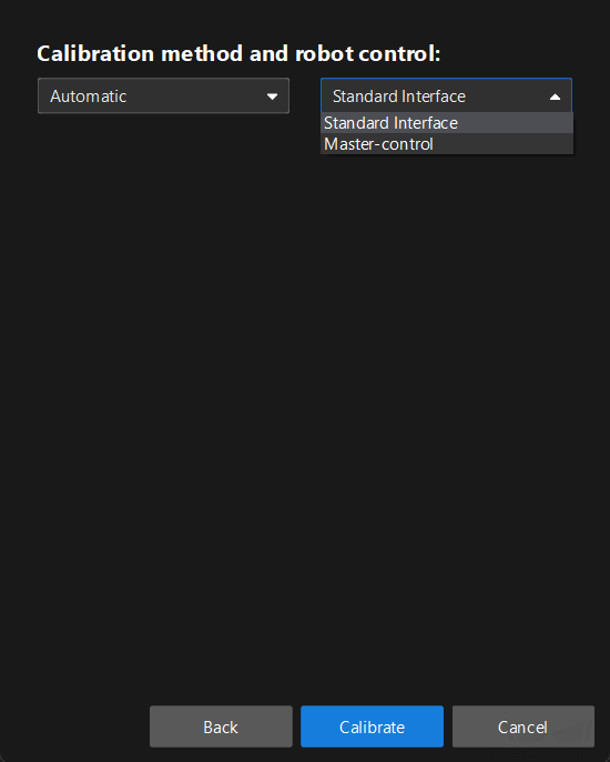
In the Calibration method and robot control window, select Automatic and Standard Interface, and then click the Calibrate button. The Calibration (Eye to Hand) window will be prompted.
Till now, you have completed the pre-calibration configuration and can start the calibration procedure.
Perform Calibration
Connect to a Camera
-
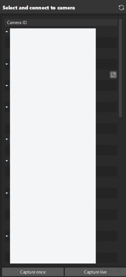
In the Connect to Camera step, find the camera to connect in the Detected Cameras list, and click
 .
.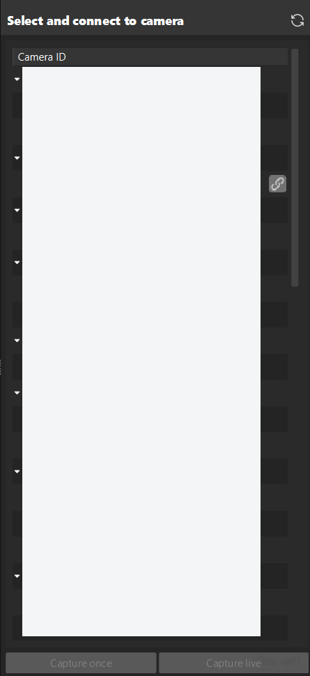
-
After the camera is connected, click the Acquire once or Acquire continuously button.
-
In the right Image viewer panel, ensure that the camera can acquire images normally and click the Next button on the bottom bar.
Mount Calibration Board & Check Intrinsic Parameters
-
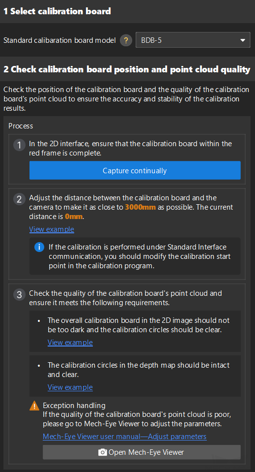
In the Mount calibration board & check intrinsic parameters step, set the Standard calibration board model parameter in the 1 Select calibration board area.
-
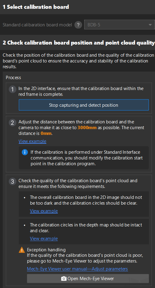
In the 2 Check calibration board position and point cloud quality area, read carefully the requirements on the calibration board position and point cloud quality, and then click the Acquire continuously button. The Acquire continuously button will turn into Stop acquisition and detect position.
-
Manually control the robot carrying the calibration board to move to an appropriate position, ensuring the calibration board is fully within the red frame, and the distance between the calibration board and the camera is as close to the recommended value on the interface as possible.
After adjusting the distance between the calibration board and the camera according to the prompts on the interface, the robot’s position can be used as the starting point for calibration. -
Ensure that the 2D image and depth map of the calibration board meet the requirements, and then click the Stop acquisition and detect position button.
If the acquired images do not meet the requirements, click Open Mech-Eye Viewer button to open the Mech-Eye Viewer software, adjust the 2D and 3D exposure parameters and re-acquire images. Please note that you need to change the Parameter group parameter to “calib” first.
-
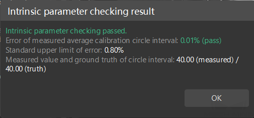
In the 3 Check intrinsic parameters area, click the Check intrinsic parameters button.
-
Confirm the results of the camera intrinsic parameter check.
-
If the camera intrinsic parameter check passes, click the OK button in the prompted window, and then click the Next button on the bottom bar.
-
If the intrinsic parameter check fails, you can draw aid circles to assist in the intrinsic parameter check, and then click the Recheck intrinsic parameters button.
-
| If the intrinsic parameter check still fails after the above operations, please contact Mech-Mind Technical Support. |
Connect to the Robot
-
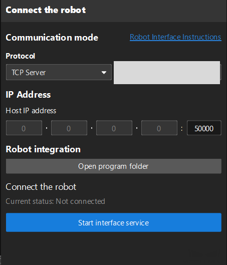
(Optional) In the Connect the robot step, click the Start interface service button. The button will turn intoWaiting for the robot to connect.... If the Robot Communication option on the toolbar was previously enabled, this step is not necessary.
-
On the robot teach pendant, select the automatic calibration program according to Robot Automatic Calibration, teach the start point and run the program. After the program is started, the log message “Entering the calibration process, please start the calibration in Mech-Vision” will be printed in the Console log panel.
-
Return to Mech-Vision, confirm that “Connected” status message is displayed in the Connect the robot area, and click the Next button.
Set Robot Path
-
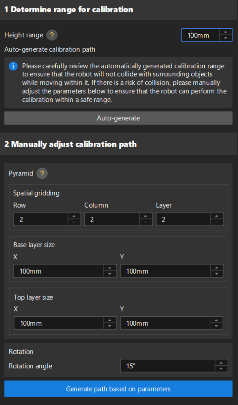
Determine the calibration range.
Set the Height range parameter. The Height range parameter should be set according to the recommended working distance range of the camera and the size of the robot’s working space. Generally, the height range is slightly larger than the height of the target object(s) to be recognized.
-
Automatically generate the calibration path (recommended).
Click the Auto-generate button, and click the OK button in the prompted window Auto align robot path to camera frame.
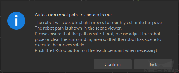
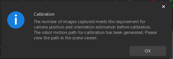
This operation will slightly move the robot and acquire images. The whole process may take 10 to 15 seconds. Please ensure that the motion path is safe. In case of emergency, please tap the emergency stop button on the robot teach pendant to stop the robot immediately. After the calibration path is generated, click OK in the pop-up Calibration window.
-
Modify the calibration path manually.
If the calibration path automatically generated in step 2 has a collision risk, you can also manually modify the calibration path by modifying the pyramid structure, re-dividing the pyramid grid, and setting the rotation angle.
-
Spatial gridding: To shorten the calibration time or if the calibration range is small, you can set two rows, two columns, and two layers.
-
Base layer size: If the space on site is sufficient, the base layer size is generally the size of the bin or pallet. If site space is limited, the base layer size can be appropriately reduced to avoid collisions.
-
Top layer size: Typically, the top layer size should be slightly smaller than the base layer size, making the calibration range a trapezoidal.
-
-
In the right Scene Viewer panel, make sure that all the waypoints are at a proper position and that the robot will not collide with surrounding objects when moving.
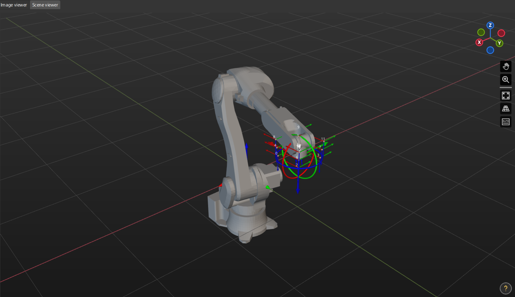
-
Click the Generate motion path based on path parameters button and then click the Next button on the bottom bar.
Obtain Images and Poses
| Before this step, please make sure that the current robot pose matches the real pose on the robot teach pendant. |
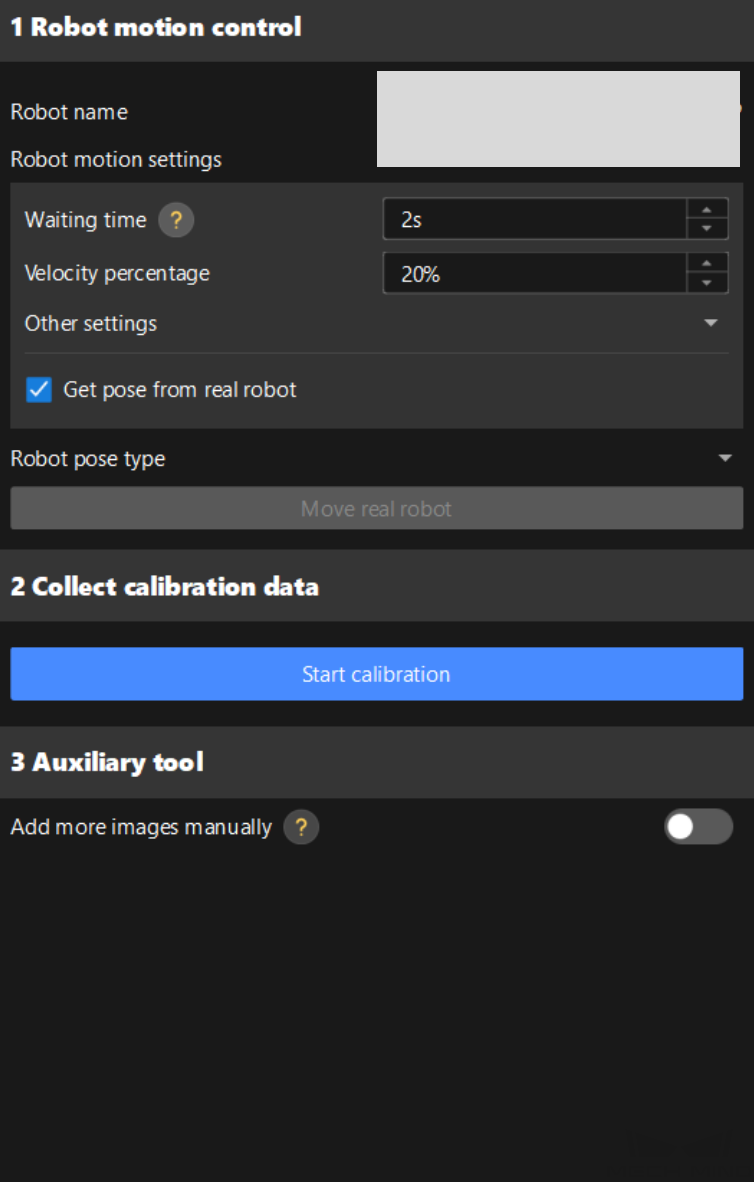
-
In the Obtain images and poses step, click the Start calibration button.
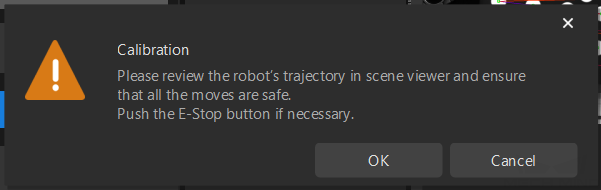
-
Read the safety window carefully and click the OK button.
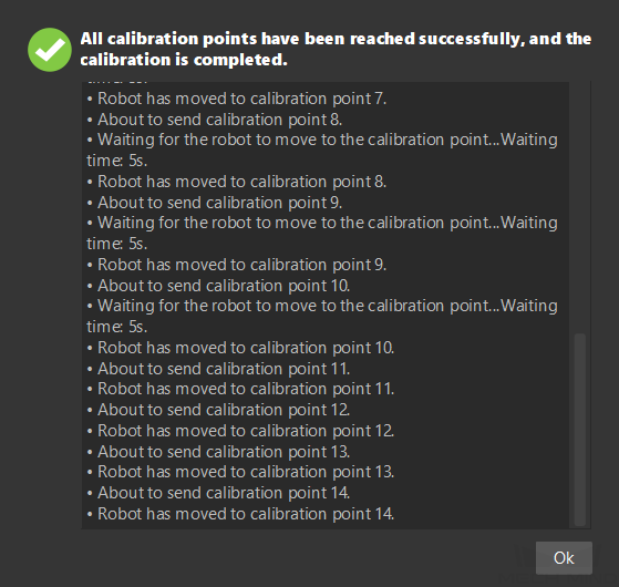
-
Wait until the robot finishes moving along the preset path and the camera finishes acquiring images on all waypoints. A pop-up window will display the progress of moving to the calibration point.
Please stay away from the robot working area to keep safe. -
When the pop-up window says “All calibration points have been reached successfully, and the calibration is completed.”, click the Ok button.
-
Confirm that the collected calibration data meets the data requirements, and then click the Next button on the bottom bar.
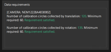
If the requirements are not met, please manually move the robot, enable the Add more images manually option in the 3 Auxiliary tool area, and click the Add images and record flange poses button to add the calibration board image and enter the robot flange pose.
Calculate Extrinsic Parameters
-
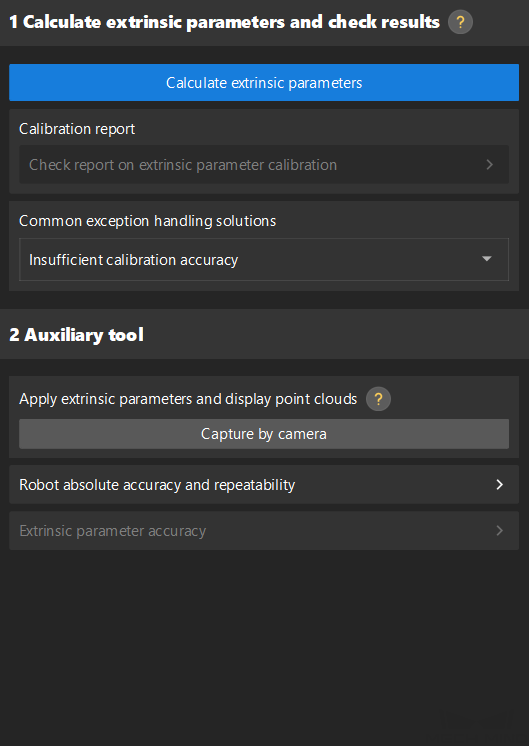
In the Calculate extrinsic parameters step, click the Calculate extrinsic parameters button in the 1 Calculate extrinsic parameters and check results area.
-
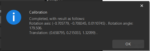
In the prompted window indicating calibration success, click the OK button.
-
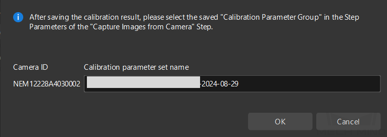
Click the Save button on the bottom bar. In the prompted Save Calibration Files dialog box, click the OK button. The camera calibration result will be automatically saved in the “calibration” directory of the project.
For details on how to validate the calibration results, please refer to Validate Calibration Results.
Now you have completed the hand-eye calibration in the eye-to-hand setup.