Picking and Placing
In this tutorial, you will first learn about the picking and placing process in this example, and then learn how to configure it.
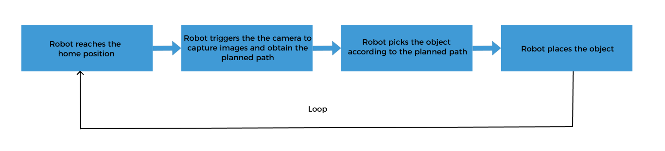
Picking and Placing Process
The picking and placing logic in this example is shown in the figure below.
Communication Solution Description
In the above process, the step “robot triggers the camera to capture images and obtain the planned path” requires the robot to use the Standard Interface to communicate with the vision system, and the Standard Interface “uses Mech-Viz to obtain the planned path” from the vision system.
When using this collaborative mode, you need to configure the Mech-Vision project (already configured in the “Vision Project Configuration” section) and Mech-Viz project, and write the robot program. Please refer to Configure the Picking and Placing Process to configure the Mech-Viz project and write the robot program.
Configure the Picking and Placing Process
To realize the logical flow of picking and placing, you need to complete the following configurations:
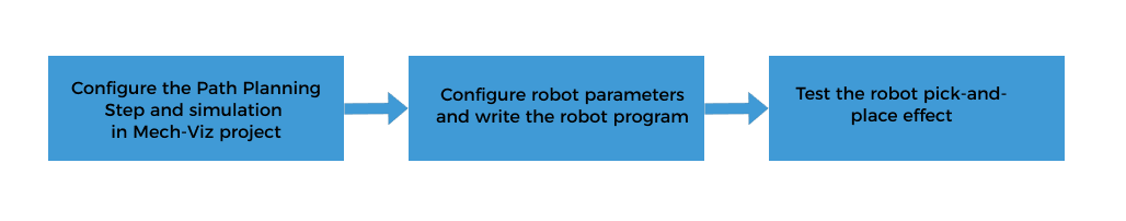
Configure the Mech-Viz Project for Path Planning and Simulation
Creating a project in Mech-Viz to provide the following functions for the robot:
-
Path planning: plans the robot’s picking path. Note that the planned path does not contain the path of placing. The placing path should be added to the robot program.
-
Collision detection: Mech-Viz performs collision detection during path planning to provide the robot with a collision-free picking path.
-
Run as simulation: Mech-Viz can visualize the picking process of the simulated robot for commissioning.
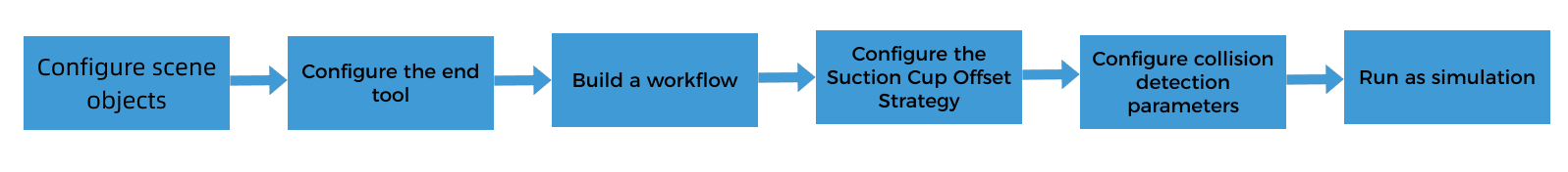
The process of configuring a Mech-Viz project is shown in the figure below.
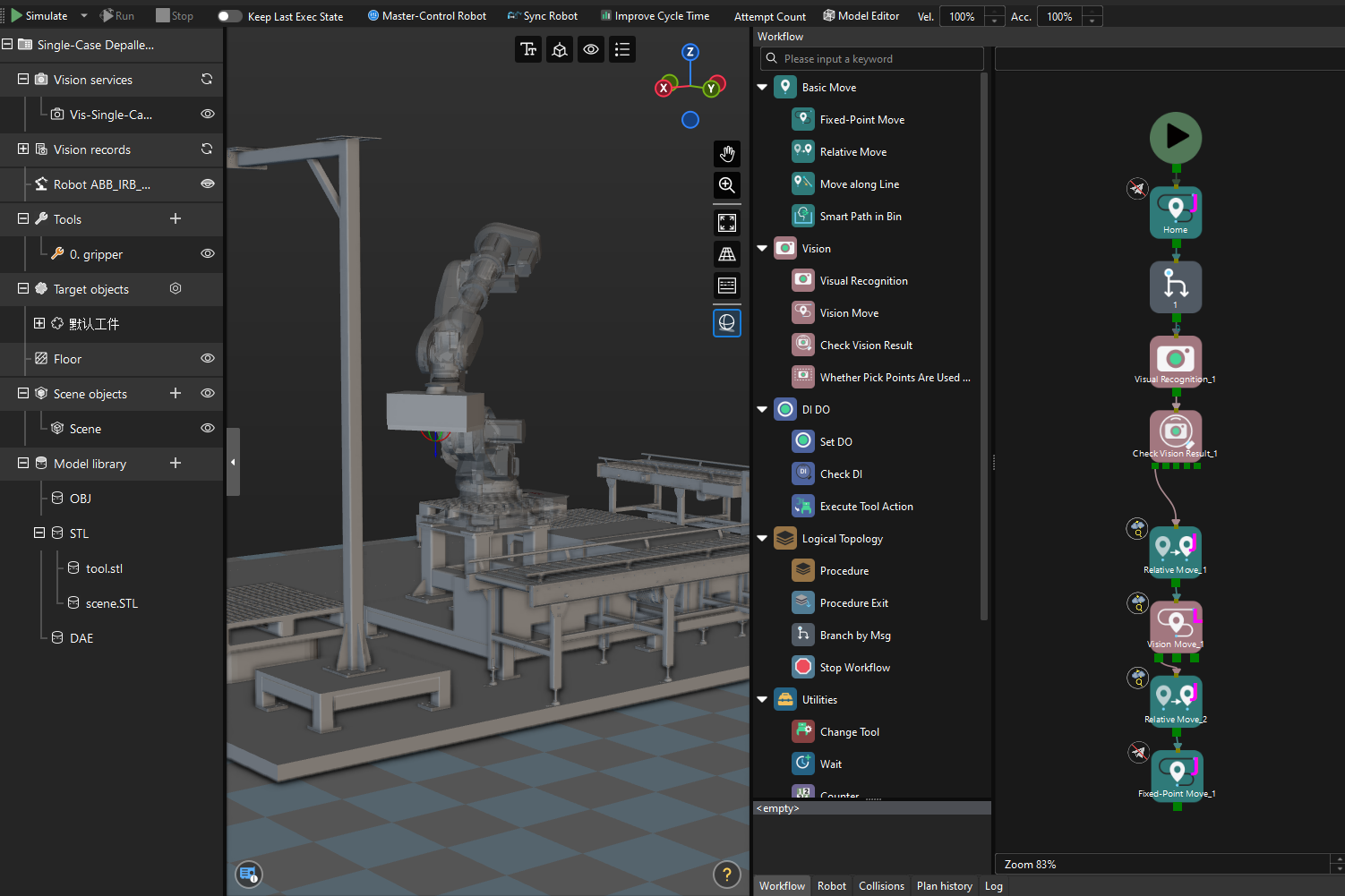
The "Single-Case Depalletizing" case in the Mech-Vision Solution Library has a built-in Mech-Viz project “Viz-Single-Case Depalletizing." Before proceeding, please open the Mech-Viz software, select in the menu bar, and select the “Viz-Single-Case Depalletizing” folder in the local “Single-Case Depalletizing” solution folder.
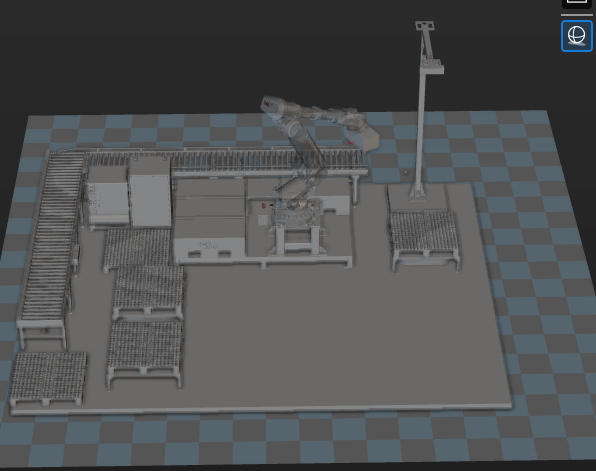
Configure Scene Objects
Scene objects are introduced to make the scene in the software closer to the real scenario, which facilitates the robot path planning. For detailed instructions, please refer to Configure Scene Objects.
On the basis of ensuring the feasibility of picking, strict restoration of the actual operating environment should be carried out. The scene objects in this solution are set as follows.
Configure the End Tool
The end tool should be imported and configured so that its model can be displayed in the 3D Simulation Area and used for collision detection. For specific operations, please refer to Configure the End Tool.
Associate the Target Object and Tool
After configuring the end tool, you need to associate the target object with the end tool for picking in the target object editor, so that the configured end tool can be used for picking. In this example, the target object to pick is a carton, and you do not need the target object model for matching. Therefore, you only need to create one target object without a point cloud model (default target object) in the target object editor.
-
Click the setting button under the Target objects node in the project resource tree to open the target object editor.
-
In the Select configuration workflow window, click the Recognize without Matching card. This operation automatically creates a default target object and adds a default pick point.
-
In the Picking configuration area of the Set pick point tab, select Use all tools in Mech-Viz to associate the end tool with the target object.
Simplify the Collision Model
To save time when creating a collision model for the end tool, you do not always replicate every detail of the original model when creating convex hulls. You can omit certain details based on the specific requirements of the model.
Model simplification guideline: Screw holes and other detail features in the gripper-robot connection section can be removed. Since the original suction cup model was a cuboid, there is no need to simplify it here.
A simplified model is shown below.

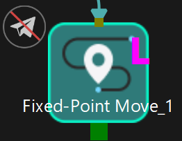
Build a Workflow
The built-in Mech-Viz project “Viz-Single-Case Depalletizing” of the “Single-Case Depalletizing” case has already created a workflow. The description of each Step in the workflow is as follows.
| Step | Description | Usage |
|---|---|---|
|
Define the image-capturing position. The image-capturing position refers to the position of the robot where the camera captures images. At this position, the robot arm should not block the camera’s FOV.
|
Only used for simulation, not sent to the robot |
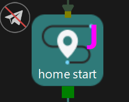
|
Chooses a branch according to the receiving message |
Waiting for the robot program to send the command to start capturing images |
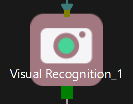
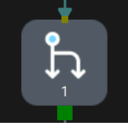
|
Calls the vision result from Mech-Vision |
/ |
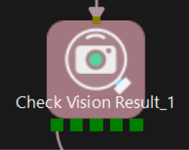
|
Checks whether there is any vision result |
/ |
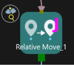
|
Plans the approach point for picking |
Sent to the robot |
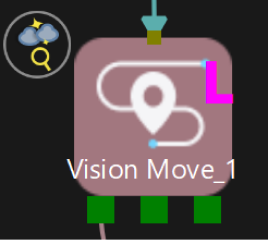
|
Plans the pick point |
Sent to the robot |
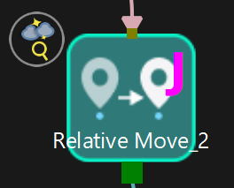
|
Plans the retreat point for picking |
Sent to the robot |
|
Defines the intermediate point |
Only used for simulation, not sent to the robot |
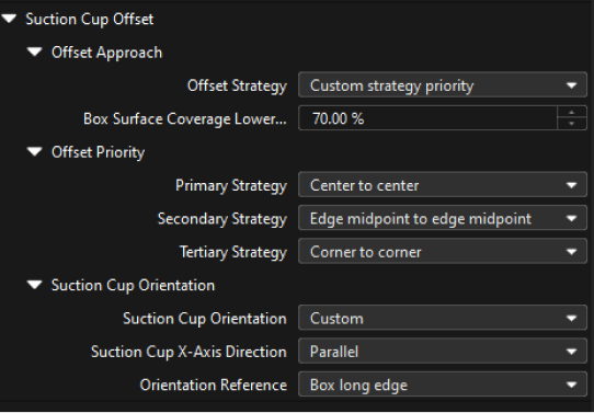
Configure the Suction Cup Offset Strategy
In the “Vision Move” Step, you can configure the suction cup offset strategy according to the on-site picking requirements.
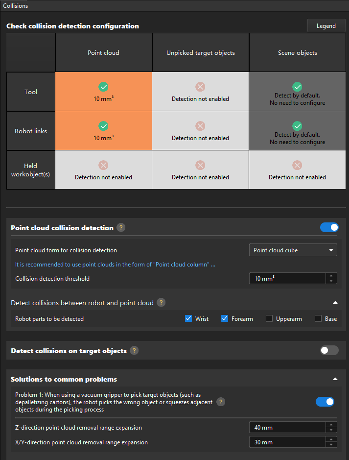
Configure Collision Detection Parameters
The Mech-Viz software can use the collision detection function to avoid unnecessary collisions when the robot is moving. Point cloud collision detection should be enabled for this application. For detailed instructions, please refer to Collision Detection Configuration.
-
In this application, enable Point cloud collision detection and set the point cloud form for collision detection to "Point cloud cube." The Point cloud collision detection function is mainly used to detect the collision between the gripper and the point cloud. You can enable the collision detection between the robot parts and point cloud according to actual requirements to reduce planning time.
-
Detect collisions on target objects is mainly used to detect the collision between the picked target object and the scene object. For carton scenarios, it does not need to be enabled.
-
Solutions to common problems: Please enable Problem 1 and set the Z-direction point cloud removal range expansion and X/Y-direction point cloud removal range expansion according to the on-site situation. Note that the X/Y-direction point cloud removal range expansion should not be set too large. Failure to do so may cause the suction cup to press against the adjacent carton during picking.
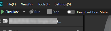
Run as Simulation
Click the Simulate button on the toolbar to run the Mech-Viz project as simulation.
Simulation and testing objectives
Place the carton on the pallet and use the Mech-Viz software to simulate picking. After each successful picking, manually remove the carton that has been successfully picked during simulation, and circulate the simulation to test a layer of cartons, If all cartons can be picked successfully, you can determine that the vision project has been built without exception.
Configure Robot Parameters and Write the Robot Program
ABB’s Standard Interface example program MM_S9_Viz_RunInAdvance can basically satisfy the requirements of this example. You can modify the example program. For a detailed explanation of the MM_S9_Viz_RunInAdvance program, please refer to the Example Program Explanation.
Based on the example program, please complete the following steps on the robot side:
-
Teach the home position (initial position).
Move the robot to the initial position in the TEACH mode. The initial position should be away from the objects to be picked and surrounding devices, and should not block the camera’s field of view. Record the current robot pose to variable home.
-
Specify the IP address and port number of the IPC. Change the IP address and port of the MM_Init_Socket command to those of the IPC.
Before modification After modification (example) MM_Init_Socket "127.0.0.1",50000,300;
MM_Init_Socket "192.168.10.111",50000,300;
-
Teach the robot the image-capturing position.
Move the robot to the image-capturing position in the TEACH mode. The image-capturing position refers to the position of the robot where the camera captures images. At this position, the robot arm should not block the camera’s FOV. Record the current robot pose to variable camera_capture.
-
Set the DO port signal to open the suction cup to pick the carton. Note that the DO command should be set according to the actual DO port number in use on site.
Before modification After modification (example) !add object grasping logic here, such as "setdo DO_1, 1;" Stop;!add object grasping logic here, such as "setdo DO_1, 1;" setDo do0, 1; !Stop; -
Teach the intermediate point and placing point.
Move the robot to the intermediate point and placing point in the TEACH mode, and record the robot pose to variables drop_waypoint and drop respectively.
-
Set the DO port signal to disable the suction cup for placing cartons. Note that the DO command should be set according to the actual DO port number in use on site.
Before modification After modification (example) !add object releasing logic here, such as "setdo DO_1, 0;" Stop;!add object releasing logic here, such as "setdo DO_1, 0;" setDo do0, 0; setDo do4, 1; Stop;
Test the Robot Pick-and-Place Effect
Follow these steps to test the robot pick-and-place effect:
-
On the teach pendant, tap .
-
Confirm that MM_S9_Viz_RunInAdvance is selected, and then click OK.
-
Press and hold the following button to power up the motor. In this case, the status icon on the teach pendant indicates that the motor is powered up.
-
Click the Run button on the teach pendant.
If the robot can successfully pick and place cartons, the robot program meets your requirements.
Reference: Modified Example Program
The final example program is as follows:
PROC Sample_9()
!set the acceleration parameters
AccSet 50, 50;
!set the velocity parameters
VelSet 50, 1000;
!move to robot home position
MoveAbsJ home\NoEOffs,v500,fine,gripper1;
!initialize communication parameters (initialization is required only once)
MM_Init_Socket "192.168.10.111",50000,300;
!move to image-capturing position
MoveL camera_capture,v1000,fine,gripper1;
!open socket connection
MM_Open_Socket;
!trigger Mech-Viz project
MM_Start_Viz 2,snap_jps;
!set branch exit port
MM_Set_Branch 1,1;
LOOP:
!get planned path, 1st argument (1) means getting pose in JPs
MM_Get_VizData 1, pose_num, vis_pose_num, status;
!check whether planned path has been got from Mech-Viz successfully
IF status <> 2100 THEN
!add error handling logic here according to different error codes
!e.g.: status=2038 means no point cloud in ROI
Stop;
ENDIF
!save waypoints of the planned path to local variables one by one
MM_Get_JPS 1,jps{1},label{1},speed{1};
MM_Get_JPS 2,jps{2},label{2},speed{2};
MM_Get_JPS 3,jps{3},label{3},speed{3};
!follow the planned path to pick
!move to approach waypoint of picking
MoveAbsJ jps{1},v500,fine,gripper1;
!move to picking waypoint
MoveAbsJ jps{2},v300,fine,gripper1;
    !add object grasping logic here, such as "setdo DO_1, 1;"
    setDo do0, 1;
    !Stop;
!trigger Mech-Viz project but not to trigger camera capturing
MM_Start_Viz 2,snap_jps;
!move to departure waypoint of picking
MoveAbsJ jps{3},v500,fine,gripper1;
!move to intermediate waypoint of placing
MoveJ drop_waypoint,v500,z50,gripper1;
!move to approach waypoint of placing
MoveL RelTool(drop,0,0,-100),v500,fine,gripper1;
!set branch exit port and trigger camera capturing when robot moves out of camera’s field of view
MM_Set_Branch 1,1;
!move to placing waypoint
MoveL drop,v300,fine,gripper1;
!add object releasing logic here, such as "setdo DO_1, 0;"
!Stop;
setDo do0, 0;
setDo do4, 1;
!move to departure waypoint of placing
MoveL RelTool(drop,0,0,-100),v500,fine,gripper1;
setDo do4, 0;
!move back to robot home position
MoveAbsJ home\NoEOffs,v500,fine,gripper1;
GOTO LOOP;
END_LOOP:
!close socket connection
MM_Close_Socket;
ENDPROC
ENDMODULENow you have deployed a 3D vision-guided single-case carton depalletizing application.