Strategy of Creating Point Cloud Model
This section introduces how to choose the method of creating a point cloud model according to the actual situation, and how to select the feature point cloud.
Choose Method of Creating Point Cloud Model
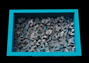
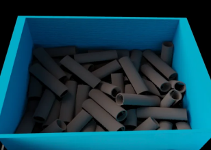
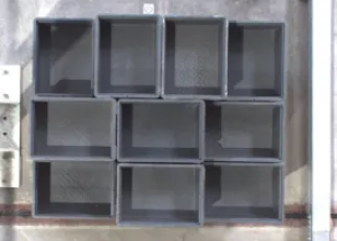
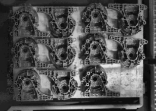
The following table lists common methods of creating a point cloud model, and describes the applicable scenarios and examples of each method.
| Methods | Suitable scenarios | Examples | |
|---|---|---|---|
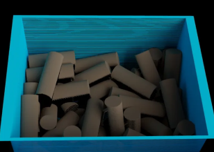
Random picking scenarios, or scenarios where the change of the target object’s pose significantly influences the point cloud features. For example, randomly placed shafts and sheet metal parts. |
|
|
|
Generate the point cloud model by acquiring point cloud with the camera |
Scenarios of picking neatly arranged objects, or scenarios where the point cloud features of the target objects do not significantly change. For example, turnover boxes and neatly arranged gearbox housings. |
|
|
Generate the point cloud model by creating a common 3D shape |
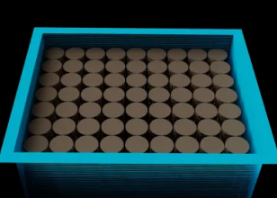
Scenarios of picking neatly arranged shafts, rings, and rectangular target objects, and picking randomly stacked shafts. |
|
|
Generate a point cloud model with the dimensions input from Step |
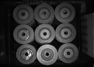
Scenarios where you need to dynamically adjust the Step parameters to switch point cloud models. For example, neatly arranged brake discs and shafts. |
|
|
|
If you choose to generate a point cloud model with the dimensions input from Step, go to the 3D Matching Step, change the Parameter Tuning Level to Advanced or Expert, and select External Model for the Input Type under Input and Output Settings. The Step will automatically display the input ports “Surface Point Cloud Model”, “Edge Point Cloud Model”, and “Object Center Point” for inputting project information. |
Select Feature Point Cloud
When creating a point cloud model, you need to remove non-critical parts of the point cloud that may interfere with matching and select the most representative parts of the point cloud as the point cloud model to optimize the subsequent matching process and improve matching efficiency and accuracy. The following section introduces how to select a feature point cloud based on the actual scenario.
Scenarios of complete point cloud
Generate point cloud model by importing STL file
Edge point cloud model
-
Symmetrical target objects
In applications, the target objects usually come in various poses, corresponding to different point clouds. Only the point cloud most representative of the edge feature of the target object should be extracted and retained in the point cloud model.
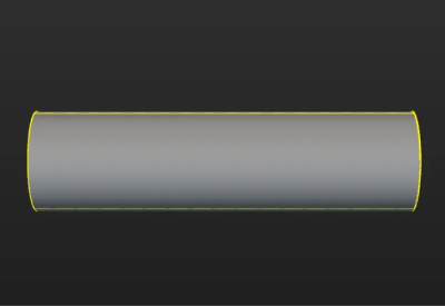
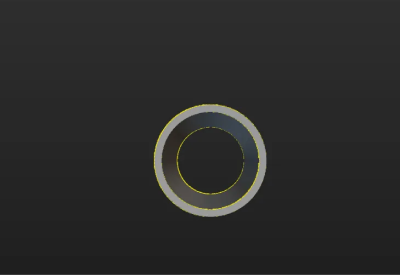
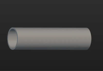
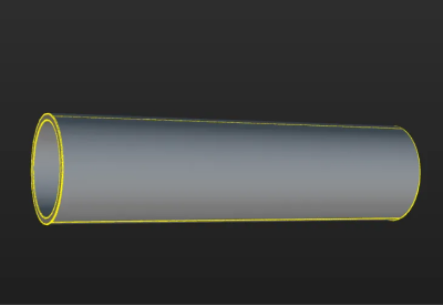
The figure below shows the edge point cloud model of the tube. The tube is symmetrical and similar to a cylinder. On the lateral area of the cylinder, only the point cloud of the edges is retained. Meanwhile, to ensure accurate positioning of the ends of the tube, the point cloud of the edges of the two ends of the tube is retained.
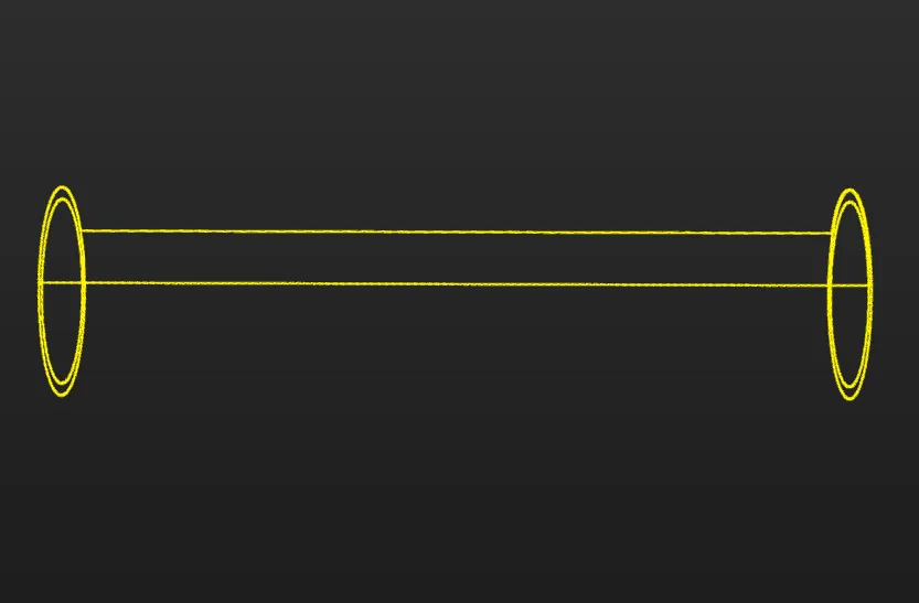
The table below shows the edge point clouds of the tube at different poses.
Tube poses Edge point clouds (in yellow) 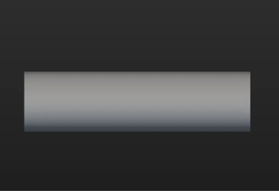

-
Asymmetrical target objects
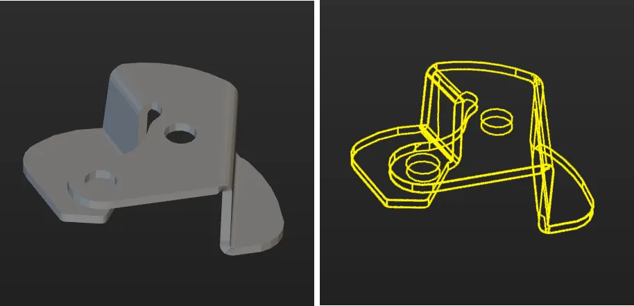
The figure below shows the edge point cloud model of the sheet metal. The sheet metal is asymmetrical, so the point cloud of all edges of the target object is retained.
Surface point cloud model
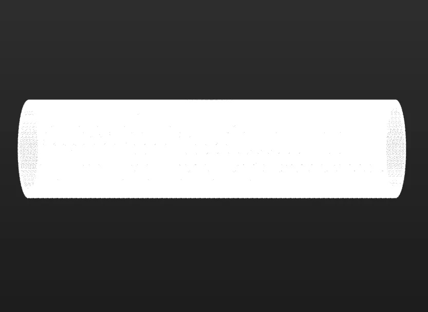
The surface point cloud model is critical in verifying the pose correctness and calculating the pose confidence. Therefore, it is recommended to use the complete surface point cloud of the target object when creating the surface point cloud model to ensure the validity. The figure below shows the surface point cloud model of the tube.
|
When using an STL model to generate a point cloud, you need to first determine whether the normals of the STL model are correct. If the normals of the STL model are incorrect, the normals of the point cloud generated from the STL model will also be incorrect, which directly affects the matching. Refer to STL Model Correction for how to check the normals of the STL model and correct the STL model. |
Generate point cloud model by acquiring point cloud with camera
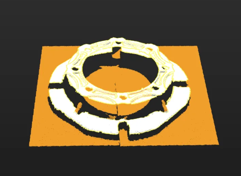
When creating a point cloud model by acquiring the point cloud of a target object with the camera, make sure that the point cloud acquired by the camera accurately reproduces the features of the target object and removes any interfering parts from the point cloud.
The figure below shows the point cloud model of a gearbox housing. The background point cloud below the housing and the cohesive point cloud (in orange) on the side should be removed.
Scenarios of point cloud loss due to reflection
Target objects with different missing parts of point cloud
When the point cloud is incomplete due to reflection on the target object surface, and the missing parts of the point clouds are different, it is challenging for the camera to acquire a complete point cloud of the target object. To effectively cope with different missing parts of point clouds during matching, it is recommended to generate the point cloud model by the Import STL file method.
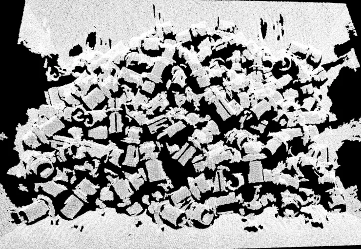
Target objects with similar missing parts of point clouds
When the point clouds of target objects have the same missing parts, it is recommended to generate the point cloud model by the Get point cloud by camera method to ensure the similarity between the scene point clouds and the point cloud model, which guarantees the matching effect and facilitates configuring the value of the confidence threshold.

Scenarios where camera’s FOV cannot cover entire object
When the camera’s FOV (field of view) cannot cover the entire target object, first ensure that the key feature point cloud used for matching is within the FOV. If necessary, remove the incomplete point clouds of the target object located at the edge of the FOV.
The figure below shows the point cloud model of a narrow, thin sheet metal. Assuming that the region marked by the red frame on the right is the camera’s FOV, it is recommended to select the point cloud within the region marked by the green frame as the point cloud model for matching stability. Make sure that the region marked by the green frame is within the camera’s FOV when acquiring data. Specifically, the right edge part should be within the camera’s FOV.

