3D Target Object Recognition (Randomly Stacked Objects)
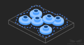
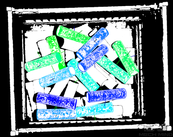
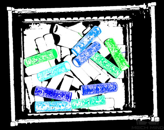
This tutorial will show you how to accurately recognize the poses of randomly stacked target objects. Taking the “3D Target Object Recognition (Randomly Stacked Objects)” project as an example, this section explains how to adjust parameters for the 3D Target Object Recognition Step and highlights key considerations for practical application.
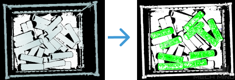
| Application scenario | Recognition result |
|---|---|
|
|
The following introduce the application guidance to the example project and key considerations for practical application.
Application Guide
In Mech-Vision’s solution library, you can find the “3D Target Object Recognition (Randomly Stacked Objects)” solution under the “3D locating” category of “Hands-on examples” and create the solution with a “3D Target Object Recognition (Randomly Stacked Objects)” project. After that, select the 3D Target Object Recognition Step and then click the Config wizard button in the Step Parameters panel to open the “3D Target Object Recognition” tool and learn how to adjust parameters. The workflow includes three processes, i.e., point cloud preprocessing, target object selection and recognition, and general settings.

-
Point cloud preprocessing: Use this process to convert the acquired image data to point clouds, set a valid recognition region, detect edge point clouds, and filter out point clouds that do not meet requirements. This process can help improve the recognition accuracy of the subsequent process.
-
Target object selection and recognition: After creating the target object model and pick points, decide whether to configure the deep learning model package and adjust the parameters for target object recognition according to the visual recognition strategy in use. Ensure that the configured parameters can meet the operational accuracy requirements so that the object recognition solution can recognize target objects stably and accurately.
-
General settings: Configure the output ports in this process by selecting data for pick points or object center points according to the requirements of subsequent picking tasks.
The following introduce the key parameters to be adjusted in each process.
Point Cloud Preprocessing
-
Set a recognition region (3D ROI). The region should fully cover the target object, with some extra space around the target object in the region.
-
In most cases, keep the default values of these parameters. If noise is still prevalent in the scene point cloud, try adjusting the relevant parameters to filter out the noise.
No more parameters need to be adjusted in this example project. You can click the Next button to proceed to the “Target object selection and recognition” process after setting the recognition region.
Target Object Selection and Recognition
After point cloud preprocessing, you need to create a point cloud model of the target object in the target object editor and then set matching parameters for point cloud model matching.
-
Create a target object model.
Click the Open target object editor button to open the editor, import the STL file to generate a point cloud model. After that, click the Save button to return to the “3D Target Object Recognition” tool interface, then click the Update target object button to select the created target object model, and apply it to recognize the poses of target objects.
You can download STL files by clicking here. -
Set parameters related to object recognition.
The following instructions on parameter adjustment is for reference only. Please adjust each parameter according to the on-site situation. -
Enable Advanced mode on the right side of Recognize target object.
-
Set the matching mode: For this project, when the Auto-set matching mode option is enabled, the recognition accuracy may not meet on-site requirements. Therefore, it is recommended to disable this option and manually adjust the relevant parameters.
Since coarse matching usually allows for some matching errors, set the Coarse matching mode to Edge matching; if the matching accuracy does not meet expectations, such as in cases of great edge point cloud fluctuation, set the Fine matching mode to Surface matching to improve the recognition accuracy.
Auto-set matching mode
Manually set relevant parameters
-
Adjust confidence settings: Adjust the Confidence settings to ensure that the uppermost normally placed tubes are accurately recognized. In this project, when the Confidence strategy is set to Auto, incorrect recognition results cannot be completely removed. Therefore, it is recommended to set this parameter to Manual and adjust the following parameters:
-
Set the Joint scoring strategy to Consider both surface and edge.
-
Since there are many coinciding points between the scene point cloud and the point cloud model, a small search radius should be selected for obtaining more accurate matching results. The Result verification degree for surface matching should be set to High, and the Surface matching confidence threshold should be set to 0.9000.
-
Since the edge point cloud of the target object model fluctuates greatly, a large search radius should be selected during recognition for more accurate matching results. The Result verification degree for edge matching should be set to Standard, and the Edge matching confidence threshold should be set to 0.5000.
Auto-set matching mode
Manually set relevant parameters
-
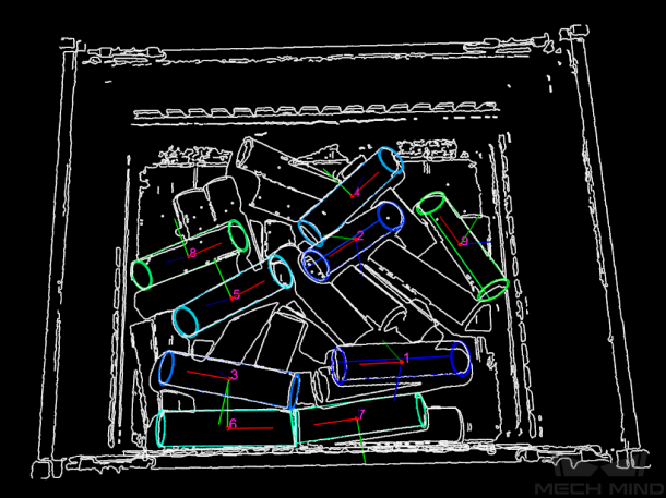
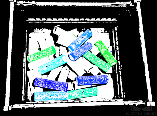
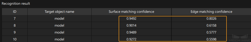
In the recognition result section at the bottom of the left-side visualization window, select Output result from the first drop-down menu. Target objects with both Surface matching confidence and Edge matching confidence values exceeding the set threshold will be retained. Please check the recognition result according to the actual situation. If there is a false recognition or false negative situation, raise or lower the respective threshold.
-
When adjusting the Confidence strategy parameter, first check the recognition result with it set to Auto. If the recognition result still does not meet on-site requirements after adjusting the Confidence threshold, and there is a significant discrepancy between the Surface matching confidence and Edge matching confidence values shown at the bottom of the visualization window, it is recommended to set the Confidence strategy to Manual and adjust the relevant parameters.
-
-
-
Max outputs under “Output”: Set this parameter value to the number of target objects when the top layer is fully exposed. In this project, the Max outputs is set to 15.
-
Upon the above, click the Next button to go to the general settings page and configure the output ports.
General Settings
After target object recognition, you can configure auxiliary functions other than visual recognition. Currently only configuring port outputs is supported, which can provide vision results and point clouds for subsequent Steps.
To ensure that objects can be successfully picked by the robot, you need to adjust the object center point so that its Z-axis points to the bin center. Under Select port, select Port(s) related to object center point. Then, select the Original point cloud acquired by camera option. The output point cloud data will be used for collision detection in path planning.
| If there are other needs on site, configure the relevant output ports according to actual needs. |
Now, you have adjusted the relevant parameters. Click the Save button to save the changes.
Key Considerations for Application
In actual applications, you should understand and consider the following, then add the 3D Target Object Recognition Step to your project, and connect the data ports to quickly and accurately recognize poses of target objects.
-
The “3D Target Object Recognition” Step is generally used in conjunction with the Capture Images from Camera Step. The Step is suitable for workpiece loading scenarios. It is capable of recognizing workpieces of various shapes and stacking methods, including separate arrangements, orderly single-layer stacking, orderly multi-layer stacking, and random stacking.
-
The “3D Target Object Recognition” Step is usually followed by a Step for pose adjustment, such as the Adjust Poses V2 Step.
This example project is to demonstrate how to accurately identify the poses of target objects when they are neatly arranged, and thus it omits the pose adjustment process.