Overview of Picking Accuracy
The purpose of this article is to explain the concept of picking accuracy, detail the various sources that can lead to picking errors, and clarify some common misconceptions about picking errors.
Introduction to Picking Accuracy
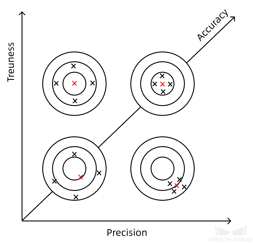
Before you dive into picking accuracy, this article clarifies three confusing concepts: trueness, precision, and accuracy.
According to the ISO 5725 standard, these three concepts are defined as follows:
-
Trueness: The closeness between the expected value of the test result and the true value.
-
Precision: The consistency of independent test results under specified conditions. It depends on the distribution of random errors and is independent of the true value or the specified value. It is usually measured using the standard deviation of the test results.
-
Accuracy: The closeness between the test result and the true value. When accuracy is used in a set of tests, it includes random errors, as well as common systematic errors and deviation components. Therefore, accuracy can be seen as a combination of trueness and precision.
The following figure illustrates the relationship between the three concepts.
In the 3D vision–guided picking scenarios, the picking accuracy is expressed as the closeness of the actual picking position of the robot to the expected picking position. It is usually expressed by picking errors. In a real project, you need to clearly define the picking accuracy requirements for your application, i.e. the allowable picking error range in the X/Y/Z direction.
The 3D vision–guided robot picking process goes through the following steps:
-
Camera captures images: First, the camera is used to capture images of the scene.
-
The vision system recognizes the target object: Through the vision system, the target object is recognized in the image.
-
The vision system outputs the picking pose: Based on the extrinsic parameters, the vision system converts the pose of the target object from the camera reference frame to the robot reference frame, and outputs the picking pose.
-
The robot picks the target object according to the picking pose: The robot performs the picking action according to the obtained picking pose.
In the picking process, errors can be introduced at each step, so the picking error is comprehensive and consists of various errors accumulated throughout the process.
The picking error mainly comes from the following aspects:
-
Camera errors
-
Robot errors
-
Extrinsic parameter errors
-
Vision recognition errors
-
Other errors (e.g. collisions, unstable mounting)
The following sections describe in detail what each error means, what causes it, and how it affects picking accuracy.
Error Sources
Camera Errors
The camera errors reflect the accuracy of the camera itself. Camera accuracy mainly includes the camera absolute accuracy and the camera repeatability.
Camera Absolute Accuracy
Camera absolute accuracy (also known as calibrated accuracy) refers to the closeness between the measured value and the true value of the distance between two points in the field of view. It equals to the trueness.
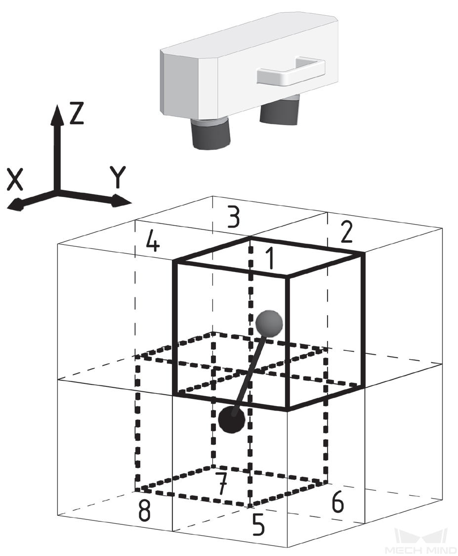
Measurement method: Use a ceramic bat as the standard gage for measurement. By using the captured point cloud of the bat, you can fit the spherical surface to calculate the spherical center coordinates and spherical centroid distance. Then you can compare the measured spherical centroid distance and the true value. The bat is placed at 7 positions in 3D space and its spherical centroid is fitted. The median and maximum spherical centroid error are calculated as absolute accuracy.
| The error is the value of the center distance error divided by the actual distance between the centers of the balls. |
The absolute accuracy of the Mech-Mind cameras is strictly checked before leaving the factory. For absolute accuracy indicators for different camera models, refer to Camera Technical Specifications.
Factors that affect the absolute accuracy of a camera may include:
-
Hardware issues: The camera itself may be faulty or damaged, such as problems with the lens, sensor, or other components.
-
Environmental changes: Changes in environmental factors such as lighting conditions, temperature, humidity, etc., may affect the performance of the camera, resulting in a decrease in absolute accuracy, such as camera temperature drift.
-
Mechanical deformation: Deformation or loosening of the mechanical structure of the camera or its mounting frame may result in instability of the camera’s position, which can affect absolute accuracy.
Camera Repeatability
The repeatability of the camera is further divided into point Z-value repeatability and region Z-value repeatability.
-
Point Z-value repeatability (1σ): One standard deviation of 100 Z-value measurements of the same point. Point Z-value repeatability is used to evaluate the accuracy of a single pixel in the Z direction.
Measurement method: A ceramic plate is used as the measurement object. After the camera reaches thermal equilibrium, it captures images of the ceramic plate 100 times at 5-second intervals. The median standard deviation of the depth value of each pixel position 100 times is calculated.
-
Z-region repeatability (1σ): One standard deviation of the Z-mean differences between the two regions measured 100 times in the depth map. Z-region repeatability (1σ) is used to evaluate the accuracy of the fit plane in the Z-direction.
Measurement method: A ceramic plate is used as the measurement object. After the camera reaches the thermal equilibrium state, it captures images of the ceramic plate 100 times at an interval of 5 seconds. One standard deviation of Z-mean differences between the two regions (200*200 pixels) 100 times is calculated.
In 3D vision–guided applications, the point Z-value repeatability is more of practical reference significance.
The main factors affecting repeatability are:
-
Working distance: The larger the working distance, the faster the repeatability decreases.
-
Hardware issues: The camera itself may be faulty or damaged, such as problems with the lens, sensor, or other components.
-
Environmental changes: Changes in environmental factors such as lighting conditions, temperature, humidity, etc., may affect the performance of the camera, resulting in a decrease in repeatability, such as camera temperature drift.
-
Mechanical deformation: Deformation or loosening of the mechanical structure of the camera or its mounting frame may result in instability of the camera’s position, which may affect repeatability.
Camera Temperature Drift
Camera temperature drift refers to the phenomenon that the thermal deformation of the components inside the camera due to temperature changes causes the camera point cloud to drift. Camera temperature drift can be caused by the following factors:
-
Stress deformation, loss, or aging of internal components.
-
Changes in the external environment, such as temperature, humidity, pressure, etc.
The temperature drift phenomenon will affect the values of each dimension of the point cloud, and affect the repeatability and absolute accuracy of the camera.
Classification of temperature drift
According to the source of temperature change, temperature drift can be divided into two categories: warm-up drift and environmental thermal drift.
-
Warm-up drift refers to the point cloud drift caused by the temperature change of the 3D camera during the cold-start process.
-
Environmental thermal drift refers to the point cloud drift caused by changes in ambient temperature and humidity.
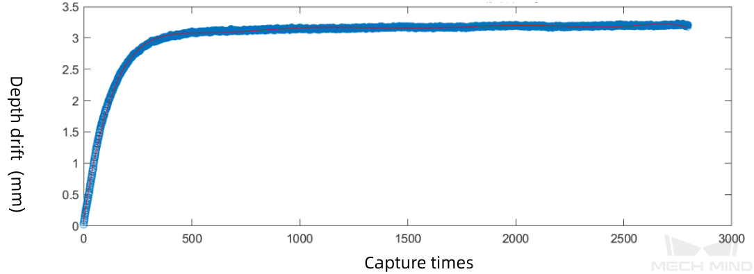
The figure below shows a typical warm-up drift curve for an LSR L-GL camera, with the vertical axis being the depth value change of the camera’s capturing plane and the horizontal axis being the number of shots. The camera captures every 5 seconds, and after about 400 captures (about 33 minutes), thermal equilibrium is reached. The depth value changes by about 3 mm when thermal equilibrium is reached.
Dealing with temperature drift
-
Preheating and warm-up: In order to reduce the occurrence of inaccurate picking, the camera needs to be preheated and warmed up when hand-eye calibration, camera intrinsic parameter calibration, intrinsic parameter correction, or calibration of other compensation parameters. You can warm up the camera by one of the following methods:
-
Connect to the camera via Mech-Eye Viewer software or Mech-Eye API and capture images continuously for more than 30 minutes. Warm-up for more than 45 minutes for high-accuracy applications;
-
Power on the camera and keep it in standby for more than 40 minutes.
-
-
Keep the temperature, humidity and pressure of the environment in which the application operates relatively stable.
-
Deploy a "System Drift Self-Correction" system: It can not only solve the problem of camera temperature drift, but also ensure the reliability and operational stability of the 3D vision system.
In addition, the stability of the camera and the camera mounting frame directly impact the camera’s absolute accuracy and repeatability.
Robot Errors
The errors related to the robot mainly include the error of the robot accuracy itself and the error of the robot model parameters.
Robot Accuracy Error
The accuracy of the robot is divided into the repeatability (positioning) accuracy of the robot and the absolute (positioning) accuracy of the robot.
-
Robot repeatability refers to the degree to which the robot’s position fluctuates when it repeatedly reaches a point in space.
-
Robot absolute accuracy refers to the deviation from the target position when the robot reaches a point in space. Measuring the difference between the set linear distance and the actual movement distance is a rough way to determine the absolute accuracy of the robot.
For applications that use the robot teach pendant to teach the motion path (non 3D vision–guided applications), the picking accuracy is only affected by the robot repeatability. In 3D vision–guided applications, however, the picking poses are input from the vision system, and the picking accuracy is mainly affected by the robot absolute accuracy.
Common factors that cause the robot absolute accuracy to decline are:
-
Robot zero position is lost.
-
TCP accuracy error.
-
The robot is not mounted securely.
Robot Zero Position Loss
When suspecting issues with the robot’s accuracy, first check if there is any offset in the zero position of each axis. Robot zero position refers to the zero position of the encoder on each axis of the robot. An offset of the zero position will lead to an error between the values of the axes on the robot teach pendant and the angles of the real robot axes. The robot absolute accuracy will be weakened if the robot zero position is lost.
Zero position loss may occur in the following conditions:
-
When a new robot was purchased, the robot manufacturer did not perform robot zero position calibration.
-
The robot lost its zero position during transportation.
-
The battery is replaced due to low battery power.
-
The robot body or controller has been replaced.
-
Encoder count data is lost.
-
Incorrect zero position calibration action was conducted.
TCP Accuracy Error
In picking applications, the robot end is usually equipped with a picking tool, such as a suction cup or gripper. The tool is considered an extension of the robot flange and can come in different shapes.
The robot system describes and controls its position based on the TCP (Tool Center Point) of the robot, and establishes a tool reference frame for the tool, thus transferring the robot’s control point to the tool.
For applications that use the teaching method to teach the robot the motion path, even applications with TCP errors will work. However, for 3D vision–guided robotic applications, the robot motion path is usually provided by the vision system, so TCP errors lead to picking errors.
The main causes of TCP errors are:
-
The definition of TCP is inaccurate.
-
The tool is not securely mounted.
Errors in Robot Model Parameters
Besides the accuracy of the robot itself, the accuracy of the robot model used by the vision system will affect the picking accuracy as well.
Mech-Viz projects use robot models for simulation and path planning. If the robot parameters are inaccurately set when the robot model is created, the robot pose and tool pose in the software will not match those of the real robot, as shown below.
| Pose of the real robot | Pose of the simulated robot |
|---|---|
|
|
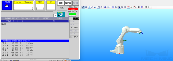
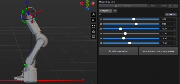
If the robot pose and tool pose in the software do not match those of the real robot, the following issues may occur:
-
Wrong robot poses were used in the hand-eye calibration, resulting in large error with the calibration results or calibration failure.
-
The vision system outputs incorrect vision results to the robot.
-
The vision system outputs incorrect waypoints to the robot, resulting in picking inaccuracy, picking failure, or collision with environmental objects.
Extrinsic Parameter Errors
Extrinsic parameters describe the pose transformation between the robot reference frame and the camera reference frame. The extrinsic parameters need to be obtained by hand-eye calibration. The error of the hand-eye calibration result is the error of the camera extrinsic parameters.
Extrinsic parameter error is also a comprehensive error that accumulates camera error, robot error, and other errors.
The main factors affecting the extrinsic parameter error are:
-
Point cloud quality.
-
Camera absolute accuracy.
-
Robot absolute accuracy.
-
Whether the calibration board is mounted securely.
-
Whether the calibration board shakes during calibration data collection.
A large error in the extrinsic parameters may lead to a large deviation between the picking pose output by the vision system and the expected picking position, leading to inaccurate picking by the robot.
Vision Recognition Error
Vision recognition errors reflect the recognition accuracy and repeatability of the vision project.
|
Vision projects usually use the following algorithms for recognition:
|
The factors that affect vision recognition error mainly include four aspects:
-
Improper deep learning result: When the training quality or parameter settings of deep learning models are improper, the recognition error may increase.
-
Unqualified 3D matching result: The inaccuracy of 3D matching algorithms or improper matching algorithm settings may reduce the accuracy of target object positioning in the 3D space, thus affecting recognition accuracy.
-
Inappropriate pose adjustment strategy: Inappropriate pose adjustment strategy may lead to incorrect pose estimation of the target object in the vision system, thus affecting the recognition accuracy and robustness. Correct pose adjustment is crucial for high-accuracy positioning.
-
Recognition repeatability error: If the vision system repeatedly performs recognition tasks, the accumulation of errors or insufficient repeatability will further affect the stability and reliability of the system. Therefore, maintaining good recognition repeatability is crucial for long-running systems.
The factors that affect the vision recognition error will be explained in detail below.
Improper Deep Learning Result
The factors that lead to improper deep learning results in the vision project include:
-
Quality of the 2D images captured by the camera: If the captured 2D image is overexposed or underexposed, it directly affects the inference result of deep learning. This issue is usually solved by adjusting the 2D exposure parameters. In the presence of strong ambient light, shading measures should be taken to improve image quality.
-
Quality of deep learning model: The quality of the acquired 2D image and the trained deep learning model directly impact deep learning inference. Clear and high-quality images for model training and representative datasets improve the deep learning result.
-
Deep learning parameter settings: Appropriate setting of deep learning parameters improves the accuracy of instance segmentation. By fine-tuning these parameters, you can adjust the model performance in different scenarios to achieve the best deep learning inference result. Periodically review and update parameter settings to accommodate possible system changes.
Unqualified 3D Matching Result
The factors that lead to unqualified 3D matching results in vision projects mainly include:
-
Point cloud quality: If the quality of the point cloud captured by the camera is poor, it directly affects the quality of the created point cloud model and scene point cloud, thus reducing the accuracy of 3D matching.
-
Accuracy of point cloud mode and pick points: Surface model and edge model provide different matching accuracy. Surface model provides higher matching accuracy, but the recognition speed is slower when the surface model is used. When making the model, you can add pick points by dragging or teaching. Pick points added by teaching are more accurate. Therefore, in scenarios where high accuracy is required, workpiece orientations are relatively consistent, and robot TCP errors are difficult to evaluate, it is recommended to add pick points by teaching to improve accuracy.
-
Setting of the matching algorithm: Inappropriate matching algorithm settings may have a negative impact on matching results and repeatability. To ensure accurate matching, correctly select and configure the matching algorithm, especially in complex scenarios and when workpiece types need to be switched. Adjust algorithm parameters in time to meet actual requirements and improve matching effect and system stability.
Inappropriate Pose Adjustment Strategy
The applicability of the pose adjustment strategy should be determined according to specific scenarios. In some cases, improper pose adjustment strategies may lead to picking errors. For example, when building a project, assuming that the workpieces are on the left side of the bin, ignoring the possibility that the workpieces may appear on the right side of the bin may lead to picking deviations.
The reasons for inappropriate pose adjustment strategy include:
-
Lack of comprehensive consideration: Sometimes, when designing pose adjustment strategies, there may be a lack of thorough consideration for various positional changes and situational differences that a workpiece might undergo. Insufficient comprehensive consideration can lead to inadequate adaptability to specific scenarios.
-
Delay in updating to environmental changes: Work environments may change due to layout modifications, equipment replacements, or alterations in how workpieces are positioned. If pose adjustment strategies are not promptly updated to reflect these changes, it can render the strategy ineffective and unable to accurately adapt to new working scenarios.
-
Lack of flexibility: Some pose adjustment strategies may be designed too rigidly, lacking the flexibility to accommodate the diversity in workpiece positions. Insufficient flexibility can result in deviations in situations that were not adequately considered.
To ensure the accuracy of pose adjustment strategies, comprehensively consider potential changes in workpiece positions and promptly update pose adjustment strategies to adapt to evolving work environments. Regularly inspect and optimize pose adjustment algorithm settings to ensure accurate adjustments in different scenarios and minimize error rates.
Recognition Repeatability Error
The recognition repeatability is a critical benchmark for the stability of a vision project, and is affected by various factors.
-
Point cloud processing: The lighting environment, material characteristics of the workpiece, and the reflective properties of surrounding objects significantly impact the effectiveness of the workpiece point cloud. To enhance the robustness of point cloud processing, comprehensively consider and adapt to different lighting conditions and object surface properties to reduce repeatability errors.
-
Hardware influence: The influence of temperature on camera hardware will affect the intrinsic parameters and extrinsic parameters of the camera and the accuracy of pose transformation. Therefore, keeping temperature changes and adjusting extrinsic and extrinsic parameters in time help ensure system stability.
-
Vision recognition method selection: The stability of the system is directly affected by whether to use instance segmentation, the matching algorithm selection, matching parameter settings, and pick point settings. Choose a vision recognition method that is suitable for specific scenarios and optimize matching parameter settings. This helps the system adapt more effectively to various working conditions.
-
Logical judgment and error prevention: The combination of logical judgment and error prevention is also crucial. Poorly designed logical judgments or error prevention functions may cause the system to handle abnormal situations improperly, thereby affecting overall stability.
Therefore, to enhance the stability of the vision project, consider and design comprehensively in aspects such as point cloud processing, pose adjustment, vision recognition method selection, and logical judgment. This reduces recognition repeatability errors, guaranteeing reliable system operation under various working conditions.
Other Errors
Errors Introduced by Insecure Camera Mounting
The error introduced by insecure camera mounting is one of the common issues in the vision system. When the camera and its mounting frame are not securely mounted, the motion of the robot or vibrations in its surroundings may cause the camera to shake, thus affecting the imaging quality. This directly affects the absolute accuracy and repeatability of the camera.
To avoid such errors, mount the camera and its mounting frame carefully at the “vision system hardware setup” stage to ensure that their structures are solid.
Errors Introduced by Insecure Robot Mounting
Insecure robot mounting may also lead to system errors. If the robot base is unstable, the robot repeatability and absolute accuracy will be reduced if the robot shakes during movement.
To solve these issues, ensure the robot is securely mounted by properly adjusting its mounting position and structure at the “vision system hardware setup” stage.
Hardware deformation
Hardware deformation is another source of error that requires attention. During production, hardware components such as the camera, robot tool, and camera mounting frame may be deformed due to collision, thus affecting the accuracy of the camera, TCP, or picking.
To avoid errors caused by hardware deformation, check the integrity of hardware components promptly and replace or repair them if deformation is detected. Regular inspection and maintenance of hardware components throughout the production process is an important measure to ensure system stability.
Picking Accuracy Remarks
For a better understanding of picking accuracy, please consider the following explanation:
-
The picking accuracy, usually represented by the picking error, refers to the closeness of the actual picking position of the robot to the expected picking position.
-
Picking errors involve the cumulative effects of errors at various picking stages and directly reflect the picking accuracy.
-
To ensure that the overall picking errors meet the accuracy requirements of a project, optimize the system by correcting these errors.
-
The goal of correcting errors is not to eliminate them, but to meet the project accuracy requirements. For example, if there is no problem with workpiece recognition, you do not need to acquire point clouds of the whole scene.
-
In practical applications, although errors cannot be completely eliminated, appropriate measures can be taken to reduce them to a reasonable level. If the errors are already at a reasonable level, you do not need a comprehensive reassessment of the issue.
-
Even if errors are identified, they cannot always be completely rectified. For example, errors in the DH parameters of some robots can be corrected by modifying the parameters, but not all robot manufacturers support this modification method.