Check the Robot Absolute Accuracy
Checking the absolute accuracy of the robot typically requires specialized equipment such as a laser tracker and calibration software. Before deploying the vision solution, you need to check the robot absolute accuracy yourself or contact the robot manufacturer to check it and output the robot absolute accuracy check report.
The evaluation of the robot absolute accuracy is highly complex. This article provides several common qualitative evaluation methods. These evaluation methods cannot replace the quantitative absolute accuracy checks of the robot.
Check Robot Zero Position
When robots leave the factory, they are typically tested using instruments to establish the standard zero position for the robot. At the standard zero position, the reference marks on each axis are aligned.
| Some robot manufacturers provide the encoder values for each axis when the robot is in the standard zero position. These value will not change until the joint motor and encoder are separated. |
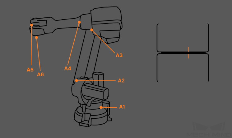
Check method: At the standard zero position, check whether the reference marks on each axis are aligned.
-
At the zero-position, if the reference marks do not have significant deviations, you can further check the consistency between the value in the teach pendant and the factory value.
-
If the reference marks are obviously not aligned, the robot accuracy requirements for high-accuracy applications cannot be met by manually calibrating the zero position. In this case, contact the robot manufacturer to get support for zero position calibration.
For more information about the calibration method, refer to Robot Zero Position Calibration posts on the community.
Check Movement Distance Error
Use the teach pendant to control the robot to move a certain distance along a fixed direction (e.g., X or Y-direction) in the workspace. After the movement, compare the theoretical distance with the actual distance the robot moved and measure the difference.
Check method:
-
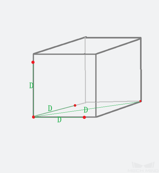
Select two points on the X/Y/Z axis and the diagonals respectively. Record the robot’s movement distance (D) on the teach pendant and measure the actual distance (D') with a ruler. Then compare the differences.
-
(Recommended) Measure the error in all three directions (XYZ) and at different positions.
Check criteria:
The smaller the overall difference, the smaller the error in movement distance, and the higher the robot absolute accuracy. Robot absolute accuracy is typically at the sub-millimeter level. If the movement distance error is too large (for example, greater than ±1 mm), please contact the robot manufacturer to calibrate the robot absolute accuracy.
Check the Accuracy of the Robot’s Seventh Axis
If the project uses a seven-axis robot (with slide rail), to verify the absolute accuracy of the seventh axis, repeatedly move the robot a fixed distance along the slide rail direction, and then check the deviation of the moving distance.
If the robot repeatability error is large (for example, a few millimeters), the accuracy of the robot’s seventh axis is poor. Contact the robot manufacturer to calibrate the robot accuracy.
Confirm Robot TCP Accuracy
Check Gripper Mounting
If the robot gripper is not mounted securely, the accuracy of TCP will be affected. Measures to ensure the secure mounting of the gripper include:
-
Suitable support structure: When selecting the support structure, consider conditions of even force distribution to ensure the structure meets the load requirements of both the gripper and the robot.
-
Using plain washers and split washers: Generally, for the connection of metal parts (made of materials with a certain level of hardness), add both plain washers and split washers. For U-shaped holes, add plain washers along with split washers.
-
Applying threadlocker: Apply threadlocker of appropriate strength, such as low-strength or medium-strength threadlocker, at the bolt connections of gripper components to enhance the fasteners' resistance to loosening.
-
Selecting proper screw length: Select screws of appropriate length based on the material and specifications of the connecting components. Ensure that the screw insertion length complies with the specifications for different materials such as aluminum and steel.
-
Screw anti-loosening marking: Apply white grease pencil marks on the screws for easy detection of the fastening status, enhancing efficiency in later inspection and maintenance.
-
Assembly principles for grouped bolts: When tightening grouped bolts, follow the principles of incremental, symmetrical, and step-by-step tightening to ensure uniform tightness of the bolts and reduce the risk of deformation in the connecting components.
-
Tightening torque requirements for threaded joint assembly: Use a standard wrench to ensure that the nut is tightened with the accurate tightening torque, preventing over-tightening and improving the firmness of the connection.
-
Deploying a Gripper Check Program to check the deformation of the gripper regularly: The gripper may be deformed due to excessive weight or long-term wear, which may lead to deviations during picking. To check whether the gripper is deformed regularly, you can deploy a Gripper Check Program. The detailed deployment is as follows:
-
Identify a fixed position in the workstation that is less affected by environmental factors.
-
Create a robot program named “Gripper Check Program”. The program should simply move the gripper (a sharp point of it) as close as possible to the fixed point. Make sure that the robot motion path remains fixed.
-
Take a picture to record the position of the gripper tip relative to the fixed point. The relative position recorded in the picture will be used as a reference standard.
-
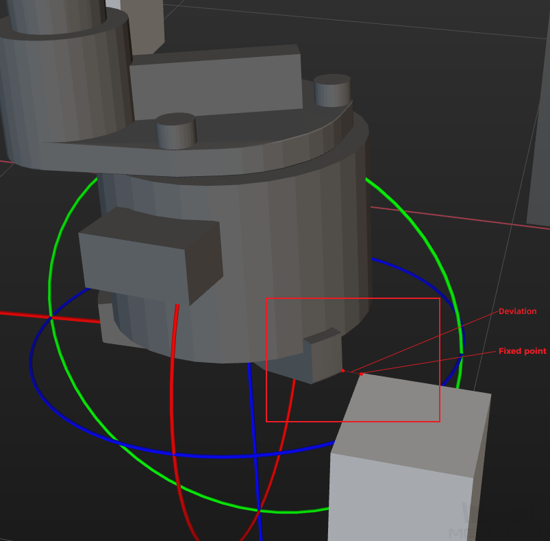
Perform visual check regularly (weekly or monthly). If a noticeable difference in relative position is detected, it indicates gripper shape change, as shown in the following figure on the right.
Relative position (standard) Relative position (with deviation) 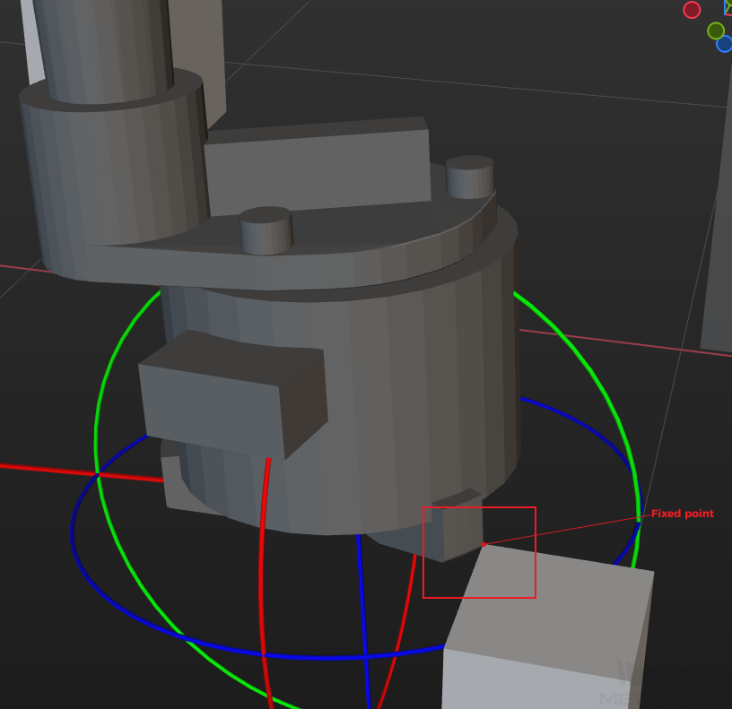
-
Evaluate TCP Accuracy
Check method:
Select the in the menu bar of Mech-Vision, and then select in the Error Analysis window.
Refer to the Check By Rotating around a Pinpoint method provided by the error analysis tool to evaluate the TCP accuracy.
The detailed instructions are shown in the figure below.
Check criteria:
If the tip of the robot flange coincides with another tip, the TCP accuracy is good; if there is a large deviation, the TCP accuracy is poor.
If the robot TCP accuracy is poor, contact the robot manufacturer to calibrate the TCP. The online community provides some posts aboutTCP calibration instructions, which are for reference only.
Check Distance between the TCP and the Point Cloud Model Center
If you want to add a pick point by teaching, check the distance from the TCP to the center of the point cloud model.
In actual projects, it is recommended to set the robot TCP near the center of the point cloud model to reduce picking errors. If the TCP is far away from the center of the point cloud model, the robot picking deviation will occur, which affects the picking accuracy.