Picking and Placing
In this tutorial, you will first learn about the picking and placing process in this example, and then learn how to configure it.
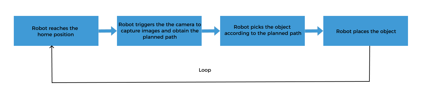
Picking and Placing Process
The picking and placing logic in this example is shown in the figure below.
Communication Solution Description
In the above process, the step “robot triggers the camera to capture images and obtain the planned path” requires the robot to use the Standard Interface to communicate with the vision system, and the Standard Interface “uses Mech-Vision to obtain the planned path” from the vision system.
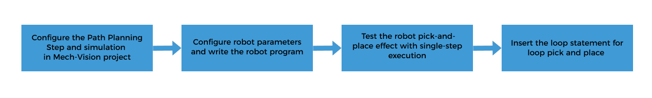
When using this mode, you need to configure the Mech-Vision project (including the “Path Planning” Step) and write the robot program. Please refer to Configuring the Picking and Placing Process to configure the Mech-Vision project and write the robot program.
Configure the Picking and Placing Process
To realize the logical flow of picking and placing, you need to complete the following configurations:
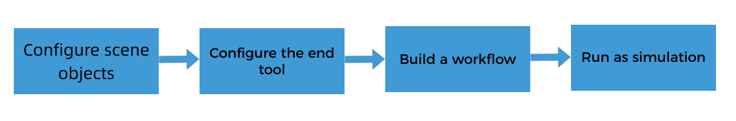
Configure the Path Planning Step and Simulation in the Mech-Vision Project
The Path Planning Step provides the following functions for the robot:
-
Path planning: plans the robot’s picking path. Note that the planned path does not contain the path of placing. The placing path should be added to the robot program.
-
Collision detection: The Path Planning Step performs collision detection during path planning to provide the robot with a collision-free picking path.
-
Run as simulation: The Path Planning Step can visualize the picking process of the simulated robot for commissioning.
| By default, collision detection between the robot, scene objects, and the tool has been enabled in the Path Planning Step. No additional collision detection parameters need to be configured in this Step. |
The workflow of configuring the Path Planning Step in a Mech-Vision project is shown below.
Click the Config wizard button on the Step block in the Graphical Programming Workspace to open the path planning configuration tool.
Configure Scene Objects
Scene objects are introduced to make the scene in the software closer to the real scenario, which facilitates the robot path planning. For detailed instructions, please refer to Configure Scene Objects.
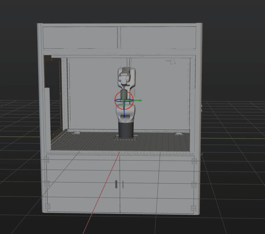
On the basis of ensuring the feasibility of picking, strict restoration of the actual operating environment should be carried out. The scene objects in this solution are set as follows.
Configure the End Tool
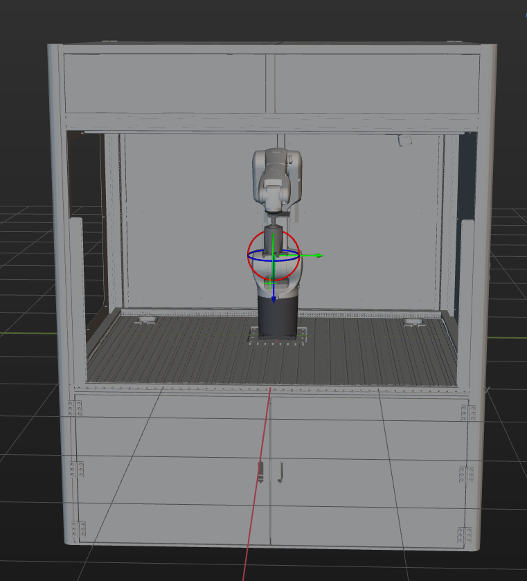
The end tool should be imported and configured so that its model can be displayed in the 3D Simulation Area and used for collision detection. For specific operations, please refer to Configure the End Tool.
Associate the Target Object and Tool
After configuring the end tool, you need to associate the target object with the end tool for picking in the target object editor, so that the configured end tool can be used for picking.
When the pick point is set by teaching, all configured end tools can be used for picking by default. Therefore, in this case, you do not need to do anything.
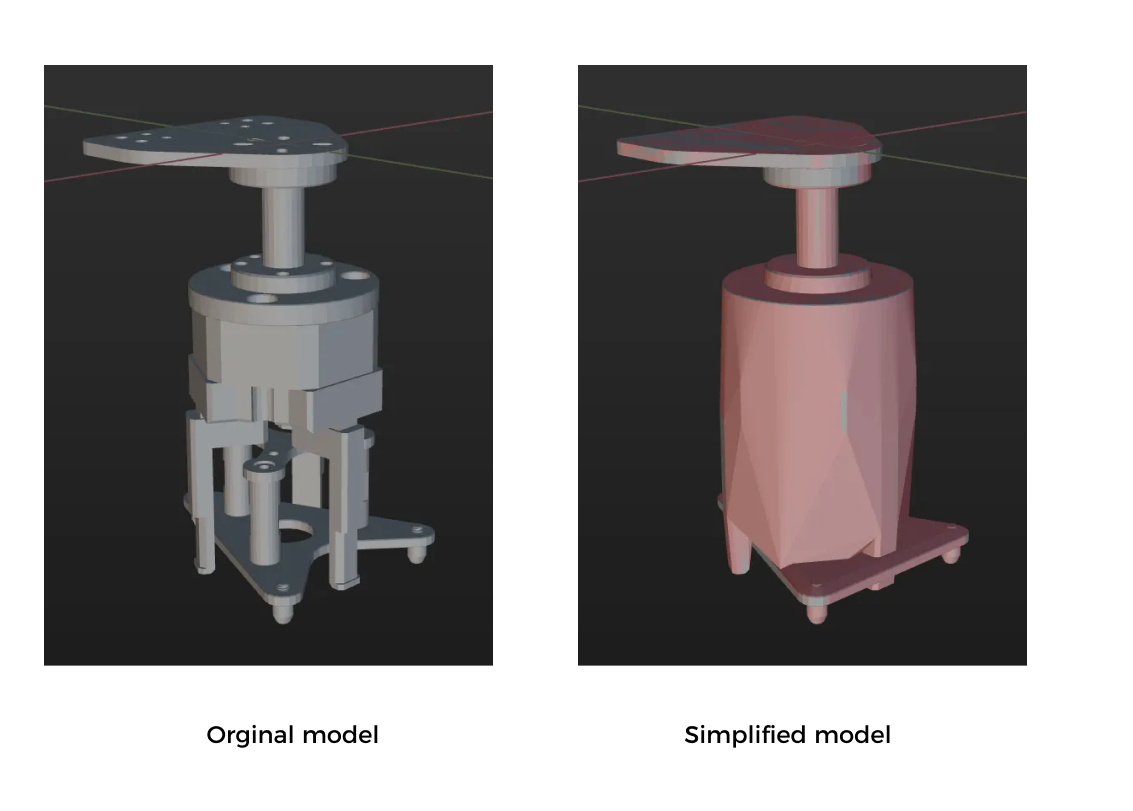
Simplify the Collision Model
To save time when creating a collision model for the end tool, you do not always replicate every detail of the original model when creating convex hulls. You can omit certain details based on the specific requirements of the model.
Simplification guideline: The gripper’s finger part should be as refined as possible to ensure that its shape can be highly reproducible to ensure the accuracy of collision detection. For mechanical structures that are far away from the finger part, you can replace the complex structural design with a cuboid bounding box to improve efficiency.
A simplified model is shown below.
Create a Workflow
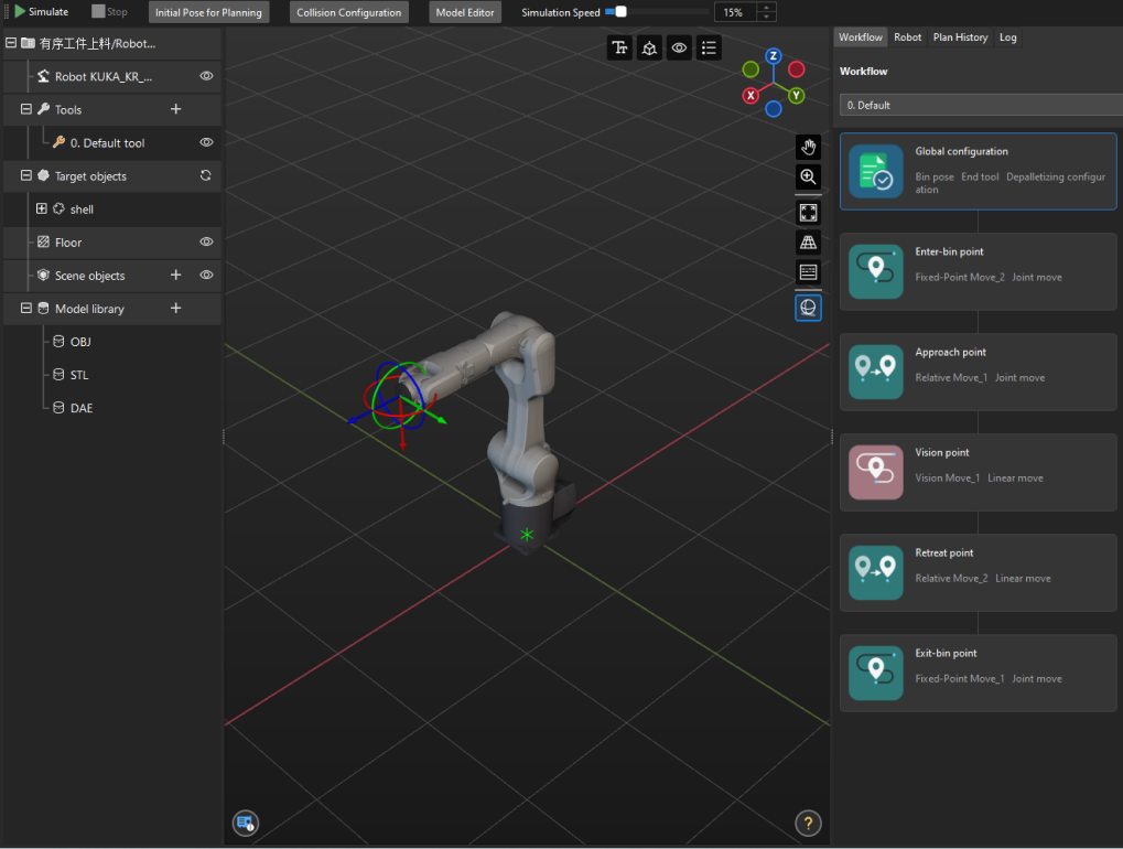
The “Path Planning” tool already has a built-in workflow. The description of each Step in the workflow is as follows.
| Step | Description | Usage |
|---|---|---|
|
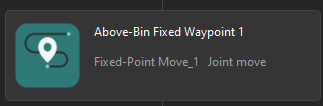
Define the image-capturing position. The image-capturing position refers to the position of the robot where the camera captures images. At this position, the robot arm should not block the camera’s FOV.
|
Only used for simulation, not sent to the robot |
|
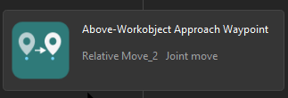
Plans the approach point for picking. |
Sent to the robot |
|
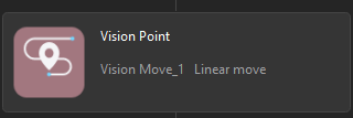
Plans the pick point. |
Sent to the robot |
|
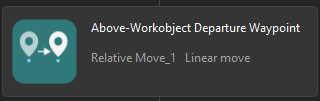
Plans the retreat point for picking. |
Sent to the robot |
|
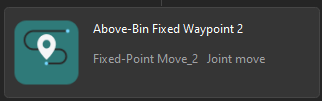
Defines the intermediate point.
|
Only used for simulation, not sent to the robot |
| In subsequent robot program writing, the image-capturing pose and intermediate point pose should be the same as those used for simulation here. |
Run as Simulation
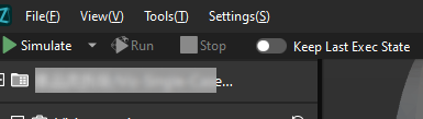
Click the Simulate button on the toolbar to run the Mech-Vision project as simulation.
Simulation and testing objectives
Place a target object randomly on a pallet, and then use Mech-Vision’s Step “Path Planning” to simulate picking. The target object should be re-arranged after each successful picking, and 3 picking loops will be simulated. If the simulated picking in 3 loops can proceed successfully, you can determine that the vision project has been built without exception.
Configure Robot Parameters and Write the Robot Program
KUKA’s Standard Interface example program MM_S3_Vis_Path can basically satisfy the requirements of this example. You can modify the example program. For a detailed explanation of the MM_S3_Vis_Path program, please refer to the Example Program Explanation.
Based on the example program, please complete the following steps on the robot side:
-
Set the tool reference frame. Verify that the TCP on the robot teach pendant matches the TCP in the "Path Planning" Step ofMech-Vision. Set the currently selected tool frame number to the one corresponding to the reference frame of the actual tool in use.
Before modification After modification BAS(#TOOL,1)
BAS(#TOOL,#)
Please replace “#” with the actual tool ID. -
Teach the home position (initial position).
Move the robot to the initial position in the TEACH mode. The initial position should be away from the objects to be picked and surrounding devices, and should not block the camera’s field of view. Record the current robot pose to variable HOME.
-
Added the commands for opening the gripper.
  $OUT[131] = True
  $OUT[132] = False
-
Specify the IP address of the IPC. The XML_Kuka_MMIND.xml configuration file is loaded to the KUKA robot when the Standard Interface program is loaded to the robot. You can modify the IP address and port of the IPC in the configuration file before loading. If they are not already modified, you can open the XML_Kuka_MMIND.xml file specified by the MM_Init_Socket command and update the IP address and port in the XML file to those of the IPC.
-
Teach the robot the image-capturing position.
Move the robot to the image-capturing position in the TEACH mode. The image-capturing position refers to the position of the robot where the camera captures images. At this position, the robot arm should not block the camera’s FOV. Record the current robot pose to variable camera_capture.
-
Set the signal for the DO port to close the gripper and pick the target object. Note that the DO command should be set according to the actual DO port number in use on site.
Before modification After modification (example) ;add object grasping logic here, such as "$OUT[1]=TRUE" halt
;add object grasping logic here, such as "$OUT[1]=TRUE" halt $OUT[131] = False $OUT[132] = True
-
Teach the intermediate point and placing point.
Move the robot to the intermediate point and placing point in the TEACH mode, and record the robot pose to pick_point3 and drop_app respectively.
-
Set the DO port signal to open the gripper to place the target object. Note that the DO command should be set according to the actual DO port number in use on site.
Before modification After modification ;add object releasing logic here, such as "$OUT[1]=FALSE" halt
;add object releasing logic here, such as "$OUT[1]=FALSE" halt $OUT[131] = True $OUT[132] = False
Test the Robot Pick-and-Place Effect with Single-Step Execution
Follow these steps to test the robot pick-and-place effect:
-
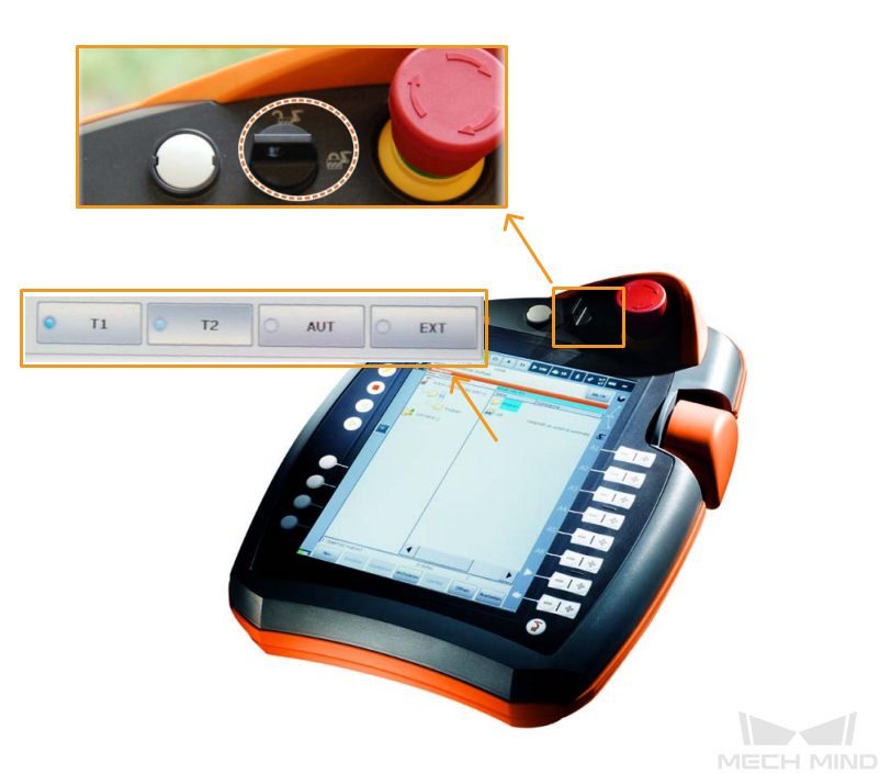
Turn the key switch on the teach pendant to horizontal, select the running mode T1 in the pop-up dialog box, and then turn the switch back to vertical.
-
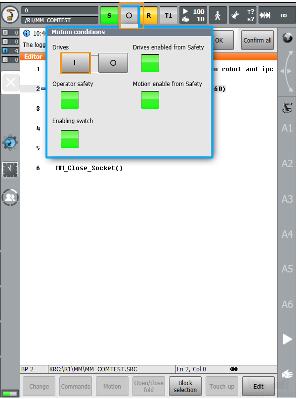
Select O. Then, select I in the pop-up window to switch the status of Drives to I. If Drives is already set to I, skip this step.
-
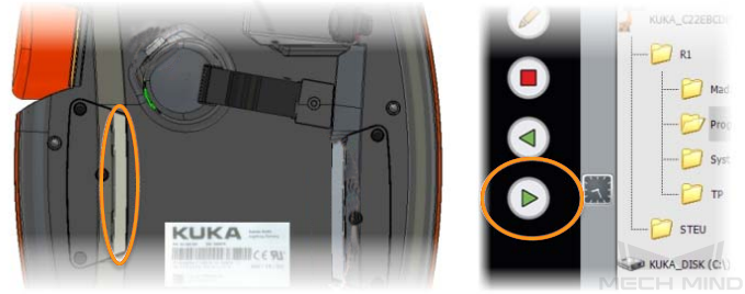
Press the white enabling switch halfway in on the back of the teach pendant and press the green start button on the front to run the program. When R turns green, the program is running.
-
The robot will automatically run the pick-and-place program to pick and place a target object.
If the robot can successfully pick and place target objects, the robot program meets the requirements.
Insert the Loop Statement for a Pick-and-Place Cycle
After testing that the robot can successfully pick and place once, you can insert a loop statement in the program (line 12 and line 61) to loop the pick-and-place process.
Add the following loop statement:
Init: ... GOTO Init
Reference: Modified Example Program
The final example program is as follows:
&ACCESS RVO
DEF MM_S3_Vis_Path ( )
;---------------------------------------------------
; FUNCTION: trigger Mech-Vision project and get
; planned path
; Mech-Mind, 2023-12-25
;---------------------------------------------------
;set current tool no. to 1
BAS(#TOOL,1)
;set current base no. to 0
BAS(#BASE,0)
Init:
;move to robot home position
PTP HOME Vel=100 % DEFAULT
$OUT[131] = True
$OUT[132] = False
;initialize communication parameters (initialization is required only once)
MM_Init_Socket("XML_Kuka_MMIND",873,871,60)
;move to image-capturing position
LIN camera_capture Vel=1 m/s CPDAT1 Tool[1] Base[0]
;trigger Mech-Vision project
MM_Start_Vis(1,0,2,init_jps)
;get planned path from NO.1 Mech-Vision project; 2nd argument (1) means getting pose in JPs
MM_Get_Vispath(1,1,pos_num,vis_pos_num,status)
;check whether planned path has been got from Mech-Vision successfully
IF status<> 1103 THEN
;add error handling logic here according to different error codes
;e.g.: status=1003 means no point cloud in ROI
;e.g.: status=1002 means no vision results
halt
ENDIF
;save waypoints of the planned path to local variables one by one
MM_Get_Jps(1,Xpick_point1,label[1],toolid[1])
MM_Get_Jps(2,Xpick_point2,label[2],toolid[2])
MM_Get_Jps(3,Xpick_point3,label[3],toolid[3])
;follow the planned path to pick
;move to approach waypoint of picking
PTP pick_point1 Vel=50 % PDAT1 Tool[1] Base[0] ;
;move to picking waypoint
PTP pick_point2 Vel=10 % PDAT2 Tool[1] Base[0] ;
   ;add object grasping logic here, such as "$OUT[1]=TRUE"
   halt
   $OUT[131] = False
   $OUT[132] = True
;move to departure waypoint of picking
PTP pick_point3 Vel=50 % PDAT3 Tool[1] Base[0];
;move to intermediate waypoint of placing
PTP drop_waypoint CONT Vel=100 % PDAT4 Tool[1] Base[0];
;move to approach waypoint of placing
LIN drop_app Vel=1 m/s CPDAT2 Tool[1] Base[0] ;
;move to placing waypoint
LIN drop Vel=0.3 m/s CPDAT3 Tool[1] Base[0] ;
   ;add object releasing logic here, such as "$OUT[1]=FALSE"
   halt
$OUT[131] = True
$OUT[132] = False
;move to departure waypoint of placing
LIN drop_app Vel=1 m/s CPDAT2 Tool[1] Base[0] ;
;move back to robot home position
PTP HOME Vel=100 % DEFAULT;
GOTO Init
ENDNow you have deployed a 3D vision–guided structured bin picking application.