Vision Project Configuration
Before using this tutorial, you should have created a solution using the “Single-Case Depalletizing” case project in the Robot Communication Configuration section.
In this tutorial, you will first learn the project workflow, and then deploy the project by adjusting the Step parameters to recognize the cartons’ poses and output the vision result.
Introduction to the Project Workflow
In this tutorial, you need to configure the vision project using Mech-Vision and Mech-Viz. The process of how to configure a vision project is shown in the figure below.
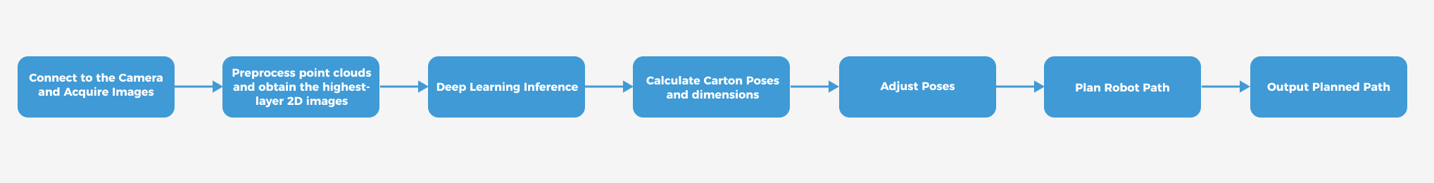
The phases of the vision project configuration process are explained below.
| Phase | Used software | Description |
|---|---|---|
Connect to the Camera and Acquire Images |
Mech-Vision |
Connect to the camera through the Mech-Vision’s “Capture Images from Camera” Step for image capturing purposes. |
Preprocess point clouds and obtain the highest-layer 2D images |
Mech-Vision |
Perform point cloud preprocessing on image data and obtain the highest layer color image through the Mech-Vision’s “Preprocess Point Clouds and Obtain the Highest-Layer 2D Images” custom Procedure. |
Deep Learning Inference |
Mech-Vision |
Use the Mech-Vision’s "Deep Learning Model Package Inference" Step to segment the highest-layer color images. |
Calculate carton poses and dimensions |
Mech-Vision |
You can use the Mech-Vision’s “Calculate Carton Poses and Dimensions” custom Procedure to calculate the poses of the highest-layer cartons. |
Adjust Poses |
Mech-Vision |
Adjust the reference frame and orientation of, sort, or filter poses output by the “3D Target Object Recognition” Step using the “Adjust Poses V2” Step of the Mech-Vision software. |
Plan Robot Path |
Mech-Vision & Mech-Viz |
The “Output” Step of Mech-Vision sends the vision result (such as object center points, scene point clouds, cartons' upper surface dimensions, etc.) to Mech-Viz.
|
Output Planned Path |
Mech-Viz |
Upon receiving the Standard Interface command from the robot (used in this tutorial) or the PLC, Mech-Viz returns the planned collision-free robot motion path.
|
Adjust Step Parameters
In this section, you will deploy the project by adjusting the parameters of each Step.
| The project in this section is "Vis-Single-Case Depalletizing" in the “Single-Case Depalletizing” solution. |
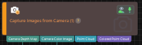
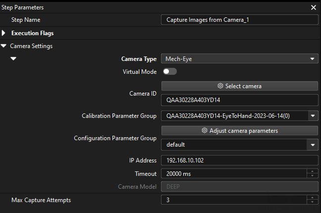
Capture Images from Camera
Step name |
Capture Images from Camera |
|---|---|
Phase |
Connect to the Camera and Acquire Images |
Illustration |
|
Description |
Connect to a real camera and configure relevant parameters to ensure that the camera can capture images normally. |
-
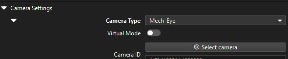
In the Graphical Programming Workspace of Mech-Vision, select the Capture Images from Camera Step, and click Select camera on the Step Parameters tab.
-
In the prompted Select camera and calibration parameter group window, click the
 icon to the right of the camera serial number. When this icon turns into an
  icon, the camera is connected successfully.
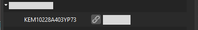
After the camera is connected, click the Select parameter group button and select the calibrated parameter group with ETH/EIH and date.
The calibration parameter group selected here is the one generated after the hand-eye calibration is completed. -
After the camera is connected and the parameter group is selected, the calibration parameter group, IP address, and ports of the camera will be obtained automatically. Make sure that Configuration parameter group is set to “Large cartons”.
-
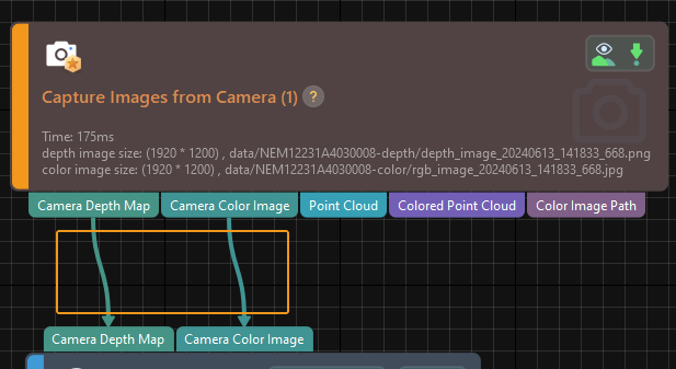
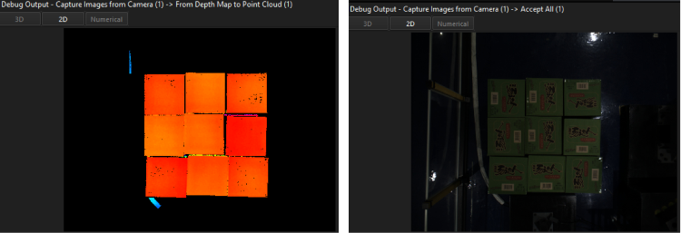
Click the Single Step Execution button of the Capture Images from Camera Step to trigger image capturing, double-click the “Camera Depth Map” and “Camera Color Image” data streams of the Step, and check whether the images were successfully captured from the camera in the Debug Output window.
-
If you can see a normal depth map and color image in the Debug Output window, the Mech-Vision software has successfully connected to the real camera and can capture images normally.
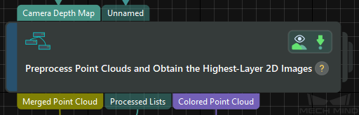
Preprocess Point Clouds and Obtain the Highest-Layer 2D Images
Step name |
Preprocess Point Clouds and Obtain the Highest-Layer 2D Images |
|---|---|
Phase |
Preprocess Point Clouds and Obtain the Highest-Layer 2D Images |
Illustration |
|
Description |
You need to set an effective recognition region (3D ROI) to keep the interference factors out of the region, and set the “Layer Height” parameter to avoid errors in extracting the 2D image of the highest layer. |
-
Set an effective recognition region (3D ROI) to keep the interference factors out of the region to improve recognition efficiency. The set 3D ROI should cover the cartons with an appropriate extension of about 50 mm to accommodate the incoming material deviation.
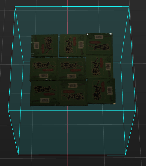
-
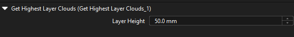
Set the “Layer Height” parameter for obtaining the highest-layer point cloud. The set parameter value should be smaller than the height of a carton and larger than the maximum height difference of the cartons on the same layer.
Deep Learning Model Package Inference
Step name |
Deep Learning Model Package Inference |
|---|---|
Phase |
Deep Learning Inference |
Illustration |
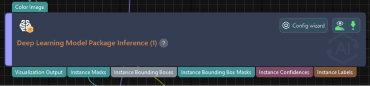
|
Description |
Import and load the deep learning model package that is built into the solution and set the 2D ROI to improve deep learning inference. |
-
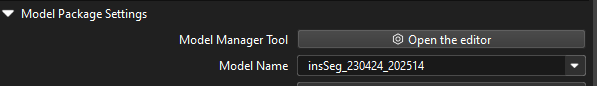
Use the Deep Learning Model Package Management tool to import the deep learning model package, and select the imported model package.
-
Set the 2D ROI for deep learning to improve deep learning inference. The set 2D ROI should cover the top-layer cartons with an appropriate margin of 1/3 to accommodate material position fluctuations.
Calculate Carton Poses and Dimensions
Step name |
Calculate Carton Poses and Dimensions (custom Procedure) |
|---|---|
Phase |
Calculate Carton Poses and Dimensions |
Illustration |
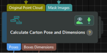
|
Description |
This Step does not require modifying parameter settings. |
Adjust Poses V2
Step name |
Adjust Poses V2 |
|---|---|
Phase |
Adjust Poses |
Illustration |
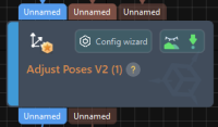
|
Description |
Set parameters to transform poses, adjust poses, sort poses, and filter poses. |
After obtaining the target object pose, you need to adjust the pose. The processing procedure is as follows.
With the built-in pose adjustment tool in Mech-Vision, you can easily adjust object poses and optimize the picking sequence. You can start parameter adjustment by opening the pose adjustment tool in either of the following ways.
-
Click the Config Wizard button on the Step block in the Graphical Programming Workspace.
-
In the Step Parameters tab, click the Config wizard button.
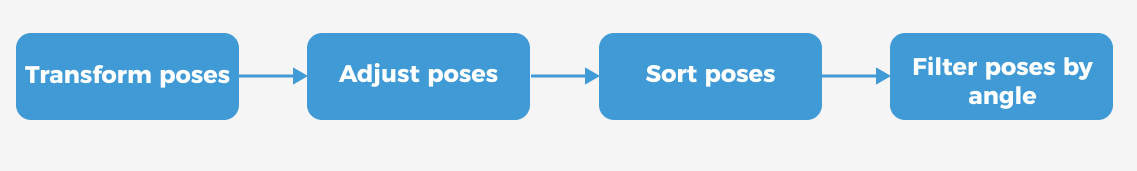
Follow these steps to adjust parameters:
-
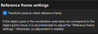
Transform poses: In the Pose adjustment tab, transform poses from the camera reference frame to the robot reference frame.
-
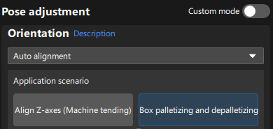
Adjust poses: In the Pose adjustment tab, set Orientation to “Auto alignment” and select the "Box depalletizing and palletizing" application scenario.
-
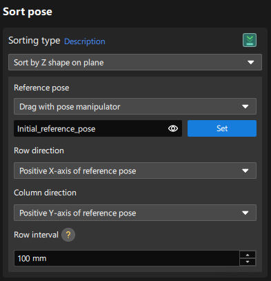
Sort poses: In the Processing rules tab, select the “Sort by Z shape on plane” sorting type, and set the row and column directions of the reference pose.
-
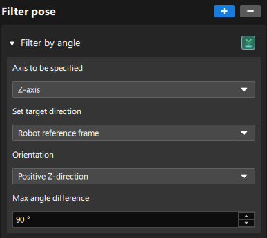
Filter poses by angle: In the Processing rules tab, filter out poses that are obviously unpickable or are false recognition results according to their Z-axis directions, reducing the time spent on path planning in Mech-Viz.
Output
Step name |
Output |
|---|---|
Phase |
Plan Robot Path (as prerequisites) |
Illustration |
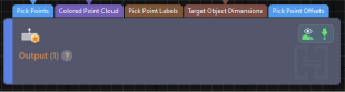
|
Description |
You need to confirm that the information needed for path planning and collision detection can be output. |
According to the requirements of path planning and collision detection, you need to output the following information to the Mech-Viz software:
-
Object center poses
-
Colored scene point cloud
-
Carton upper surface dimensions
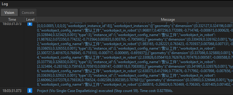
Please make sure that all the above ports have data flow connections, and then click the Run button to confirm that the project can run successfully and output the vision result. You can check whether there are logs with vision results in the Vision tab of Mech-Vision’s log panel.
Path Planning
In this example, Mech-Viz is used to obtain the planned path. When using the Standard Interface communication mode, the Mech-Viz project and the robot side need to cooperate to implement the 3D vision-guided robot picking and placing process.
For details on how to configure the Mech-Viz project for path planning, please refer to the section Picking and Placing.
Now you have completed configuring the vision project.