Vision-Guided Positioning and Assembly
This tutorial introduces how to deploy a 3D vision–guided positioning and assembly application using the application template case of “High-Precision Positioning and Assembly” in the Solution Library.
Application scenario: The 3D vision system guides the robot to assemble picked bolts into pin holes.
Application Overview
-
Target object: pin hole
This application uses a real camera to capture images of pin holes for target object recognition. If you want to use a virtual camera, please click here to download image data of the pin holes.
-
Camera: Mech-Eye PRO M-GL camera, mounted in eye to hand (ETH) mode.
-
Calibration board: When the working distance is 1000 to 1500 mm, it is recommended to use the calibration board CGB-035; when the working distance is 1500 to 2000mm, it is recommended to use the calibration board CGB-050.
-
Robot: a six-axis robot. This application uses YASKAWA_GP8 as an example.
-
IPC: Mech-Mind IPC STD
-
Software: Mech-Vision & Mech-Viz 2.2.1, Mech-Eye Viewer 2.6.0
-
Communication solution: Standard Interface communication, in which the vision system outputs pick points recognized by the Mech-Vision software.
|
If you are using a different camera model, robot brand, or target object than in this example, please refer to the reference information provided in the corresponding steps to make adjustments. |
Deploy a Vision-Guided Robotic Application
The deployment of the vision-guided robotic application can be divided into six phases, as shown in the figure below:
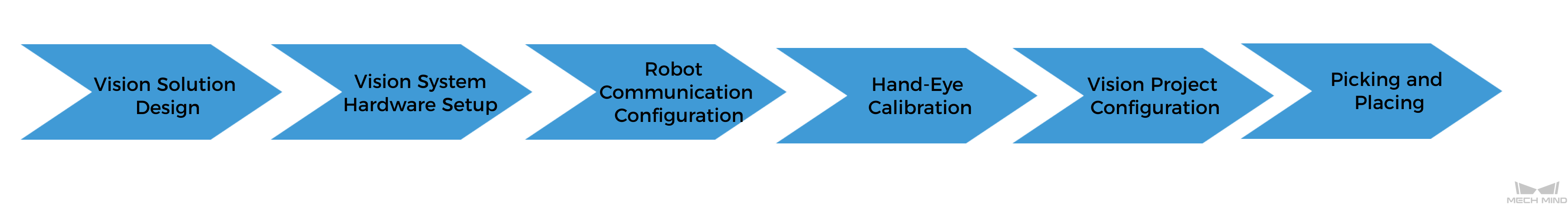
The following table describes the six phases of deploying a vision-guided robotic application.
| No. | Phase | Description |
|---|---|---|
1 |
Vision Solution Design |
Select the hardware model according to the project requirements, determine the mounting mode, vision processing method, etc. (This tutorial has a corresponding vision solution, and you do not need to design it yourself.) |
2 |
Install and connect hardware of the Mech-Mind Vision System. |
|
3 |
Loaded the robot Standard Interface program and the configuration files to the robot system to establish the Standard Interface communication between the Mech-Mind vision system and the robot. |
|
4 |
Perform the automatic hand-eye calibration in the eye-to-hand setup, to establish the transformation relationship between the camera reference frame and the robot reference frame. |
|
5 |
Use the application template “High-Precision Positioning and Assembly” in Mech-Vision Solution Library and plan the robot path with the “Path Planning” Step. |
|
6 |
Based on the robot example program MM_S1_Vis_Basic, write a pick-and-place program suitable for on-site applications. |
Next, follow subsequent sections to complete the application deployment.