Vision-Guided Loading Randomly Stacked Target Objects
This tutorial introduces how to deploy a 3D vision–guided random bin picking application, using the application template case “Loading Randomly Stacked Target Objects” in the Solution Library.
Application scenario: The 3D vision system guides the robot to pick target objects randomly stacked in bins or pallets and place them on conveyor lines/secondary positioning platforms, tipping platforms, and so on.
Application Overview
-
Target object: target objects that are randomly stacked. The application uses bolts as an example.
-
This application uses the STL model file of the target object to make the target object model. Therefore, you need to prepare an STL model file for the target object in advance. You can download it by clicking here.
-
This application uses a real camera to capture images of the bolts for target object recognition. If you want to use a virtual camera, please click here to download image data of the bolts.
-
This application uses deep learning for recognition assistance, so you need to prepare a deep learning model package for deep learning inference. You can click here to download the trained deep learning model package.
-
-
Camera: Mech-Eye PRO S-GL camera, mounted in eye to hand (ETH) mode.
-
Calibration board: When the working distance is 500 to 800 mm, it is recommended to use the calibration board model CGB-035; when the working distance is 800 to 1000 mm, it is recommended to use the calibration board CGB-035.
-
Robot: a six-axis robot. This application uses FANUC_LR_MATE_200ID as an example.
-
IPC: Mech-Mind IPC STD
-
Software: Mech-Vision & Mech-Viz 2.2.1, Mech-Eye Viewer 2.6.0, Mech-DLK 3.0.1
-
Communication solution: Standard Interface communication, in which the vision system outputs the path planned by the Mech-Viz software.
-
End tool: gripper
For this application, you are required to prepare a model file in .obj format for the gripper, which will be used for collision detection during path planning. You can download it by clicking here.
-
Scene object: scene object model
This application requires a scene model file in .stl format, which is used to simulate a real scene and is used for collision detection in path planning. You can download it by clicking here.
|
If you are using a different camera model, robot brand, or target object than in this example, please refer to the reference information provided in the corresponding steps to make adjustments. |
Deploy a Vision-Guided Robotic Application
The deployment of the vision-guided robotic application can be divided into six phases, as shown in the figure below:
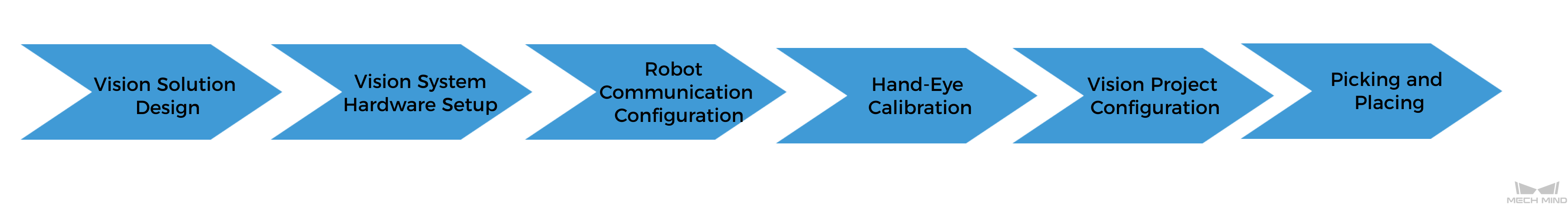
The following table describes the six phases of deploying a vision-guided robotic application.
| No. | Phase | Description |
|---|---|---|
1 |
Vision Solution Design |
Select the hardware model according to the project requirements, determine the mounting mode, vision processing method, etc. (This tutorial has a corresponding vision solution, and you do not need to design it yourself.) |
2 |
Install and connect hardware of the Mech-Mind Vision System. |
|
3 |
Loaded the robot Standard Interface program and the configuration files to the robot system to establish the Standard Interface communication between the Mech-Mind vision system and the robot. |
|
4 |
Perform the automatic hand-eye calibration in the eye-to-hand setup, to establish the transformation relationship between the camera reference frame and the robot reference frame. |
|
5 |
Use the application template “Loading Randomly Stacked Target Objects” in Mech-Vision Solution Library and plan the robot path with the “Path Planning” Step. |
|
6 |
Based on the robot example program MM_S2_Viz_Basic, write a pick-and-place program suitable for on-site applications. |
Next, follow subsequent sections to complete the application deployment.