Vision Project Configuration
Before using this tutorial, you should have created a solution using the “Loading Randomly Stacked Target Objects” case project in the Robot Communication Configuration section.
In this tutorial, you will first learn the project workflow, and then deploy the project by adjusting the Step parameters to recognize the target objects’ poses and output the vision result.
| In this tutorial, you will need to convert the STL model file of the target object into a point cloud matching model. Since it takes a long time to prepare the STL model file, it is recommended to prepare the STL model file of the target object before using this tutorial. You can download it by clicking here. |
Introduction to the Project Workflow
In this tutorial, you need to configure the vision project using Mech-Vision and Mech-Viz. The process of how to configure a vision project is shown in the figure below.
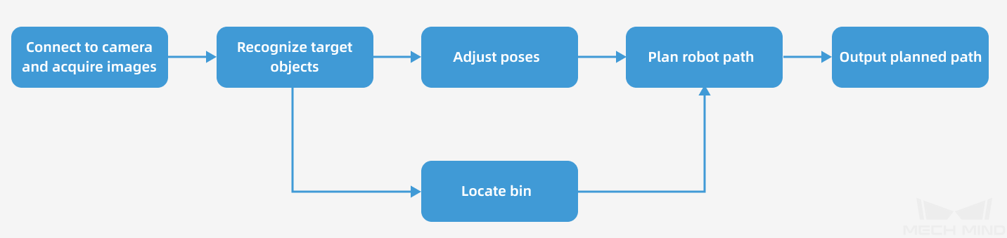
The phases of the vision project configuration process are explained below.
| Phase | Used software | Description |
|---|---|---|
Connect to the Camera and Acquire Images |
Mech-Vision |
Connect to the camera through the Mech-Vision’s “Capture Images from Camera” Step for image capturing purposes. |
Recognize Target Objects |
Mech-Vision |
Perform a series of vision processing (point cloud preprocessing, 3D matching, deep learning inference, etc.) on image data through the Mech-Vision’s “3D Target Object Recognition” Step to quickly recognize target objects. |
Adjust Poses |
Mech-Vision |
Use the “Adjust Poses V2” Step of the Mech-Vision software to transform the reference frame, adjust poses, sort poses, or filter poses output by the “3D Target Object Recognition” Step. |
Locate Bin |
Mech-Vision |
You can use the Mech-Vision’s “Standard Bin Locating” Procedure to recognize the bin. The recognized bin pose will be sent to the Mech-Viz software for updating the bin model position. |
Plan Robot Path |
Mech-Vision & Mech-Viz |
The “Output” Step of Mech-Vision sends the vision result (such as object center points, preprocessed point clouds, scene model names of bins, bin center poses, etc.) to Mech-Viz.
|
Output Planned Path |
Mech-Viz |
Upon receiving the Standard Interface command from the robot (used in this tutorial) or the PLC, Mech-Viz returns the planned collision-free robot motion path.
|
Adjust Step Parameters
In this section, you will deploy the project by adjusting the parameters of each Step.
| The project in this section is the “Vis_Target_Objects_Recognition” project in the “Loading Randomly Stacked Target Objects” solution. |
Capture Images from Camera
Step name |
Capture Images from Camera |
|---|---|
Phase |
Connect to the Camera and Acquire Images |
Illustration |
|
Description |
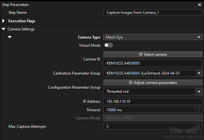
Connect to a real camera and configure relevant parameters to ensure that the camera can capture images normally. |
-
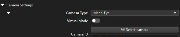
In the Graphical Programming Workspace of Mech-Vision, select the Capture Images from Camera Step, and click Select camera on the Step Parameters tab.
-
In the prompted Select camera and calibration parameter group window, click the
 icon to the right of the camera serial number. When this icon turns into an
  icon, the camera is connected successfully.
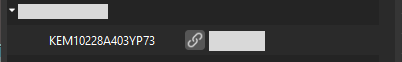
After the camera is connected, click the Select parameter group button and select the calibrated parameter group with ETH/EIH and date.
The calibration parameter group selected here is the one generated after the hand-eye calibration is completed. -
After the camera is connected and the parameter group is selected, the calibration parameter group, IP address, and ports of the camera will be obtained automatically. Make sure that Configuration parameter group is set to “Threaded rod”.
-
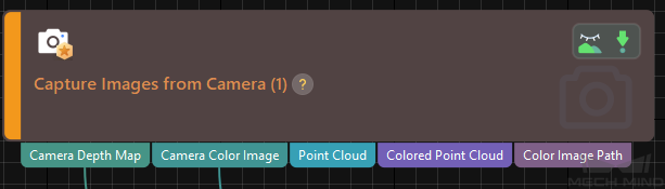
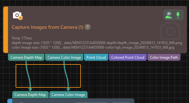
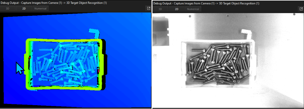
Click the Single Step Execution button of the Capture Images from Camera Step to trigger image capturing, double-click the “Camera Depth Map” and “Camera Color Image” data streams of the Step, and check whether the images were successfully captured from the camera in the Debug Output window.
-
If you can see a normal depth map and color image in the Debug Output window, the Mech-Vision software has successfully connected to the real camera and can capture images normally.
3D Target Object Recognition
Step name |
3D Target Object Recognition |
|---|---|
Phase |
Recognize Target Objects |
Illustration |
|
Description |
You need to set point cloud preprocessing parameters, make target object models in the target object editor, select the target object, set deep learning and recognition parameters, and configure output ports. |
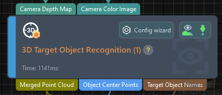
The "3D Target Object Recognition" Step provides a built-in visual "3D Target Object Recognition" tool. With the wizard, you can easily recognize target object poses in only three steps.

You can start parameter adjustment by opening the "3D Target Object Recognition" tool in either of the following ways.
-
Click the Config Wizard button on the Step block in the Graphical Programming Workspace.
-
In the Step Parameters tab, click the Config wizard button.
Point Cloud Preprocessing
Point cloud preprocessing converts the acquired image data to point clouds, detects edge point clouds, and filters out point clouds that do not meet the rules by setting valid point cloud recognition regions, thus improving subsequent recognition efficiency.
In this step, you need to set an effective recognition region to keep the interference factors out of the region to improve recognition efficiency. The recognition region should cover the bin and the target objects inside it, with an appropriate outward extension of 20 to 30 mm to accommodate the effects of minor changes in the bin position.
Usually, keep the default values of other preprocessing parameters. If there are many noises in the scene, you can try adjusting relevant parameters. For details, refer to Point Cloud Preprocessing.
| After parameter adjustment, you can click the Run Step button in the Preview preprocessing result area, and confirm that the preprocessing effect meets expectations in the Visualizing Space. |
Target Object Selection and Recognition
|
Make the Target Object Model
In this tutorial, a point cloud model of the target object is generated using the target object’s STL model file in .stl format. You can download it by clicking here.
Please refer to Import STL File to Generate Point Cloud Model and Configure Pick Points Manually to make the point cloud matching model for the target object.
Precautions:
-
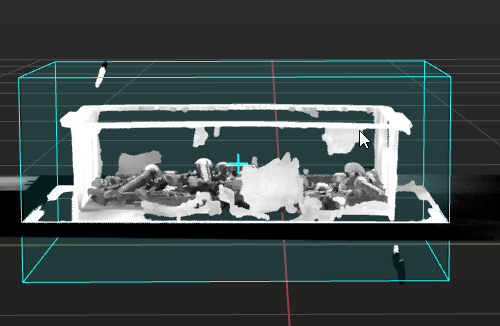
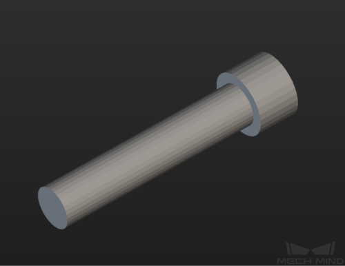
When the camera is used to acquire the point cloud data of the bolts, excessive smoothing of the point cloud may occur, which may lead to loss of thread details. Therefore, this tutorial generates the point cloud model by importing an STL file. In this tutorial, the provided STL model file has been simplified, as shown below.
-
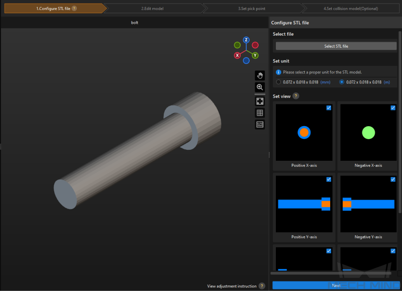
In the “Configure STL file” step, set unit according to the actual length of the target object, and select all views in the Set view area.
-
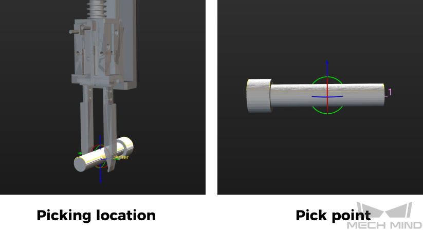
In the “Set pick point” step, set a pick point for the point cloud model according to the actual situation. For detailed instructions, please refer to Set Pick Point. In this solution, a finger gripper is used to pick the part of the screw, so the pick point of the target object is set in the middle of the screw.
| Configurations related to the end tool used for picking target objects can be suspended until the Mech-Viz project is configured. |
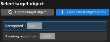
After the target object model is created, close the Target Object Editor window to return to the "3D Target Object Recognition" tool interface, and click the Update target object button. If there is only one target object model in the target object editor of the solution, the tool will automatically select the target object model. If there are multiple target object models in the target object editor of the solution, please select the target object model to use.
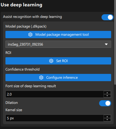
Set Deep Learning Parameters
-
In the Use deep learning area, enable the Assist recognition with deep learning option.
-
Use the model package management tool to import the deep learning model package provided in this tutorial, or you can use Mech-DLK to train your own deep learning model package. For detailed instructions, please refer to Import the Deep Learning Model Package.
-
In the Use deep learning area, select the imported model from the drop-down list of model packages.
It may take some time to load the deep learning model for the first time. Please wait patiently. -
Click the Set ROI button to set the 2D ROI. For detailed instructions, please refer to Instructions for Setting 2D ROI.
-
Adjust deep learning parameters: To avoid information loss on the edges of the masks output by the deep learning model, dilate the masks by 5 pixels to obtain more complete point cloud data of the target object.
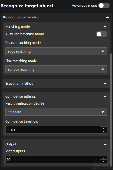
Set Matching Parameters
-
In the Recognize target object area, disable the Auto-set matching mode option. When the Auto-set matching mode option is enabled, the recognition accuracy may not meet on-site requirements. Therefore, it is recommended to disable this option.
-
Set Coarse matching mode to "Edge matching" and Fine matching mode to "Surface matching."
Considering that the surface of the bolt has many undulations, “Surface matching” should be used in the Fine matching mode. Meanwhile, it is recommended to set Coarse matching mode to "Edge matching" to use edge features more effectively to solve axial misalignments and improve matching speed. -
Set the confidence threshold, such as 0.5, according to actual needs to remove incorrect matching results.
-
Set Max outputs according to actual needs, such as 30. Minimize the number of outputs to reduce matching time while satisfying the path planning requirements.
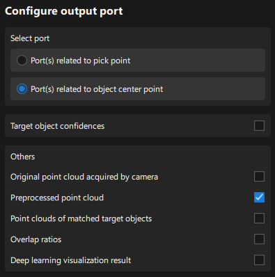
Configure Output Ports
Select the following output ports for subsequent path planning and collision detection:
-
Port(s) related to object center point
In subsequent adjustments of the poses, it will be more accurate to adjust the poses based on the center point of the target object, so you need to select this option. -
Preprocessed point cloud
The position of the bin may change with each incoming, so you need to select this option for bin recognition and locating.
Adjust Poses V2
Step name |
Adjust Poses V2 |
|---|---|
Phase |
Adjust Poses |
Illustration |
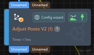
|
Description |
Set parameters to transform poses, adjust poses, sort poses, and filter poses. |
After obtaining the target object pose, you need to adjust the pose. The processing procedure is as follows.

With the built-in pose adjustment tool in Mech-Vision, you can easily adjust object poses and optimize the picking sequence. You can start parameter adjustment by opening the pose adjustment tool in either of the following ways.
-
Click the Config Wizard button on the Step block in the Graphical Programming Workspace.
-
In the Step Parameters tab, click the Config wizard button.
Follow these steps to adjust parameters:
-
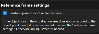
Transform poses: In the Pose adjustment tab, transform poses from the camera reference frame to the robot reference frame.
-
Adjust poses: In the Pose adjustment tab, point the Z-axis of the poses to the reference pose directly above the bin.
As the bolts are randomly stacked, if the target objects' poses are pointing upward along the Z-axis, the robot is prone to collide with the bin when picking target objects near the bin edge. Therefore, the Z-axis of the bolt poses needs to be rotated by a certain angle, and the “Point to Reference Point” strategy can achieve this effect. 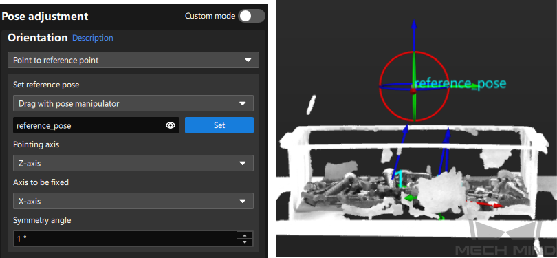
-
Sort poses: In the Processing rules tab, sort poses by their Z values in the robot reference frame in descending order.
For this application, target objects with higher heights need to be picked first, so they need to be sorted in descending order by the Z values of the poses. 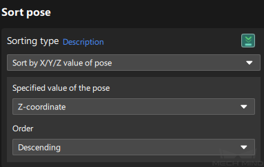
-
Filter poses by angle: In the Processing rules tab, filter out poses that are obviously unpickable according to their Z-axis directions, reducing the time spent on path planning in Mech-Viz.

-
Filter out poses out of ROI: In the Processing rules tab, set an ROI to determine whether the poses are in the ROI and keep only the poses in the ROI.
The target region (3d_roi) is in the robot reference frame. To avoid filtering errors, you must reset the target region according to the actual extrinsic parameters.
-
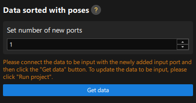
Set new ports: Set the Set number of new ports parameter to 1 to output the names of target objects corresponding to sorted poses for subsequent collision detection. Return to the graphical programming workspace and you will find a new input port and output port for receiving and outputting the target object names. Please connect the input and output ports, return to the pose adjustment tool, and click the Get data button to confirm that the parameters have been obtained correctly.
Standard Bin Locating
Step name |
Standard Bin Locating (custom Procedure) |
|---|---|
Phase |
Locate Bin |
Illustration |
|
Description |
Please set the name of the scene object that the bin will pose in the Mech-Viz project and the offset of the bin pose. |
-
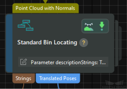
In the Mech-Vision Graphical Programming Workspace, select the Standard Bin Locating Procedure, and in the Step Parameters tab in the lower-right corner of the interface, set the Strings parameter.
The value of the Strings parameter will be used as the name of the "bin" scene object in the Mech-Viz project. The value of this parameter must be used as the name when configuring the bin scene object in the Mech-Viz project. 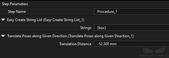
-
Set the Translation distance parameter to half the height of the bin.
The pose of the currently recognized bin is on the top surface of the bin. To ensure that the pose of the recognized bin can correspond to the center of the bin correctly, the recognition pose needs to be adjusted. This Procedure moves along the Z-axis of the bin reference frame, so a specific offset needs to be subtracted. Therefore, it is set to a negative value here.
Output
Step name |
Output |
|---|---|
Phase |
Plan Robot Path (as prerequisites) |
Illustration |
|
Description |
Confirm that the information needed for path planning and collision detection can be output. |
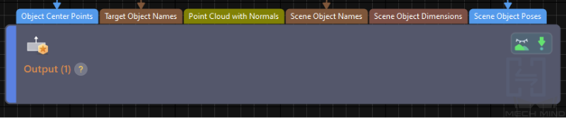
According to the requirements of path planning and collision detection, you need to output the following information to the Mech-Viz software:
-
Object center point (PoseList)
-
Target object name (StringList)
-
Point cloud with normals (Cloud(XYZ-Normal)): preprocessed point cloud
-
Scene object name (StringList): the name of the bin scene model
-
Scene object pose (PoseList): the bin center pose
Set the Port Type parameter to "Predefined (vision result)" and select the Update Scene Object option.
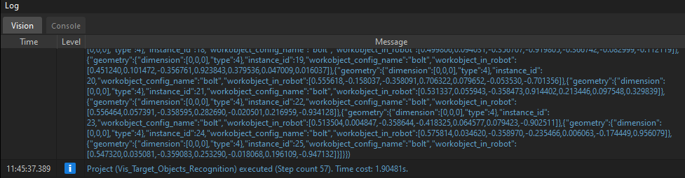
Please make sure that all the above ports have data flow connections, and then click the Run button to confirm that the project can run successfully and output the vision result. You can check whether there are logs with vision results in the Vision tab of Mech-Vision’s log panel.
Path Planning
In this example, Mech-Viz is used to obtain the planned path. When using the Standard Interface communication mode, the Mech-Viz project and the robot side need to cooperate to implement the 3D vision-guided robot picking and placing process.
For details on how to configure the Mech-Viz project for path planning, please refer to the section Picking and Placing.
Now you have completed configuring the vision project.