Picking
The ultimate goal of deploying a 3D vision–guided application is to achieve successful picking. In this phase, you need to build a robot-picking workflow so that the robot can pick objects accurately based on vision results.
Depending on the different robot communication modes selected, the way to build the workflow also varies, as shown in the figure below.
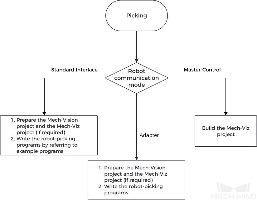
| If the project requires a high picking accuracy, ensure a good picking accuracy of the application during deployment according to the guidance in Topic: Improving Picking Accuracy. |
Build the Picking Workflow in the Standard Interface Communication Mode
If you have chosen to use the Standard Interface communication mode, you need to write a robot picking program for the robot side so that the robot can perform picking tasks under the vision guidance. Mech-Mind offers Standard Interface example programs for supported robots, and you can refer to those programs to write your robot picking program.
When Standard Interface communication is used, the cooperation between Standard Interface and the vision system can be divided into three categories according to the created project and the output result of the vision system:
The following sections introduce the three types of cooperation in detail.
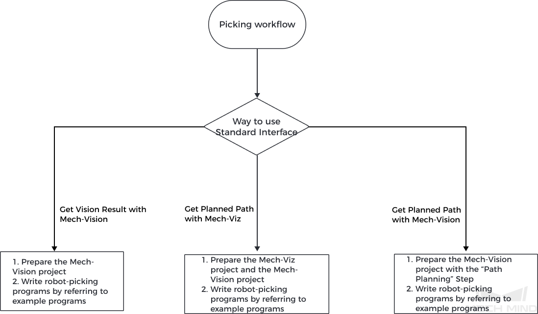
Get Vision Result with Mech-Vision
This mode is used when the robot or PLC triggers the Mech-Vision project and obtains the vision result from Mech-Vision through the Standard Interface commands.
Project to create |
Mech-Vision project |
|---|---|
Result output by the vision system |
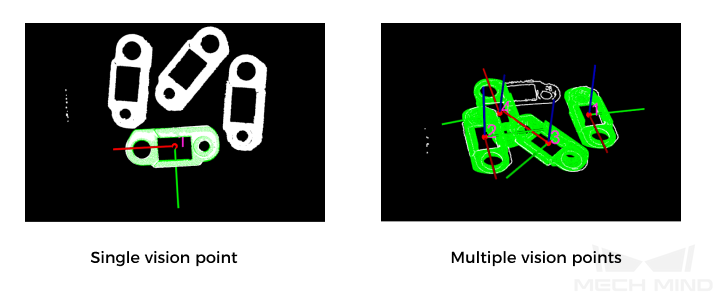
Vision result, which can contain one or more vision points, each including pose, target object information, etc.
|
| The vision result is output by the Output Step of the Mech-Vision project. Note that the Port Type parameter of the Step should be set to Predefined (vision result) or Custom. |
The general workflow of using this mode is as follows:
-
The robot or PLC triggers the Mech-Vision project to run through a Standard Interface command.
-
The vision system runs the Mech-Vision project and outputs the vision result.
-
The robot or PLC obtains the vision result through a Standard Interface command.
-
The robot picks under the guidance of the vision result.
You need to write a robot or PLC program to implement the above process. Mech-Mind provides abundant example programs for supported robots or PLCs. Among these example programs, the first one follows the above process. In addition, you can refer to other example programs for more extended functions. For more information about writing robot or PLC programs, refer to Standard Interface Communication.
Get Planned Path from Mech-Viz
This mode is used when the robot or PLC triggers the Mech-Viz project and obtains the planned path from Mech-Viz through the Standard Interface commands.
Project to create |
Mech-Viz and Mech-Vision projects |
|---|---|
Result output by the vision system |
Planned path, consisting of a series of waypoints, each containing data such as robot pose, target object information, motion type, etc.
|

|
The general workflow of using this mode is as follows:
-
The robot or PLC triggers the Mech-Viz project to run through a Standard Interface command.
-
The vision system runs the Mech-Viz project and outputs the planned path. When running the Mech-Viz project, Mech-Viz will call the Mech-Vision project to obtain the vision result and then plan the robot motion path based on the vision result.
-
The robot or PLC obtains the planned path through a Standard Interface command.
-
The robot picks under the guidance of the planned path.
You need to write a robot or PLC program to implement the above process. Mech-Mind provides abundant example programs for supported robots or PLCs. The second example program follows the above process. In addition, you can refer to other example programs for more extended functions. For more information about writing robot or PLC programs, refer to Standard Interface Communication.
Get Planned Path from Mech-Vision
This mode is used when the robot or PLC triggers the Mech-Vision project and obtains the planned path from Mech-Vision through the Standard Interface commands.
Project to create |
Mech-Vision project |
|---|---|
Result output by the vision system |
Planned path, consisting of a series of waypoints, each containing data such as robot pose, target object information, motion type, etc.
|
|
The general workflow of using this mode is as follows:
-
The robot or PLC triggers the Mech-Vision project to run through a Standard Interface command.
-
The vision system runs the Mech-Vision project and outputs the planned path.
-
The robot or PLC obtains the planned path through a Standard Interface command.
-
The robot picks under the guidance of the planned path.
You need to write a robot or PLC program to implement the above process. Mech-Mind provides abundant example programs for supported robots or PLCs. The third example program follows the above process. In addition, you can refer to other example programs for more extended functions. For more information about writing robot or PLC programs, refer to Standard Interface Communication.
Build the Picking Workflow in the Master-Control Communication Mode
If you have chosen to use the Master-Control communication mode, you can build the robot picking workflow (that is the Mech-Viz project) in a graphical manner in Mech-Viz.
For details on how to build a Mech-Viz workflow, please refer to Build a Mech-Viz Workflow.