Vision Project Configuration
Before using this tutorial, you should have created a solution using the “High-Precision Positioning and Assembly” case project in the Robot Communication Configuration section.
In this tutorial, you will first learn the project workflow, and then deploy the project by adjusting the Step parameters to recognize the target objects’ poses and output the vision result.
Introduction to the Project Workflow
In this tutorial, you need to configure the vision project with Mech-Vision. The process of how to configure a vision project is shown in the figure below.
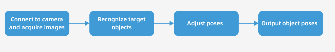
The phases of the vision project configuration process are explained below.
| Phase | Used software | Description |
|---|---|---|
Connect to the Camera and Acquire Images |
Mech-Vision |
Connect to the camera through the Mech-Vision’s “Capture Images from Camera” Step for image capturing purposes. |
Recognize Target Objects |
Mech-Vision |
Perform a series of vision processing (point cloud preprocessing, 3D matching, etc.) on image data through the Mech-Vision’s “3D Target Object Recognition” Step to quickly recognize target objects. |
Adjust Poses |
Mech-Vision |
Use the “Adjust Poses V2” Step of the Mech-Vision software to transform the reference frame, sort poses, or filter poses output by the “3D Target Object Recognition” Step. |
Output Target Object Poses |
Mech-Vision |
When the Standard Interface command sent by the robot (used in this tutorial) or the PLC is received, the“Output” Step of Mech-Vision returns the vision result (the pick point of the target object).
|
Adjust Step Parameters
In this section, you will deploy the project by adjusting the parameters of each Step.
| The project in this section is “High-Precision Positioning and Assembly” in the “High-Precision Positioning and Assembly” solution. |
Capture Images from Camera
Step name |
Capture Images from Camera |
|---|---|
Phase |
Connect to the Camera and Acquire Images |
Illustration |
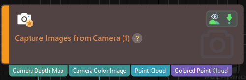
|
Description |
Connect to a real camera and configure relevant parameters to ensure that the camera can capture images normally. |
-
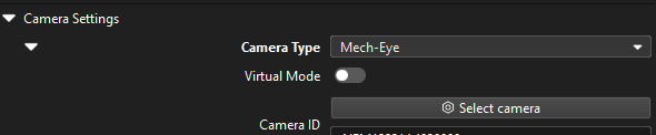
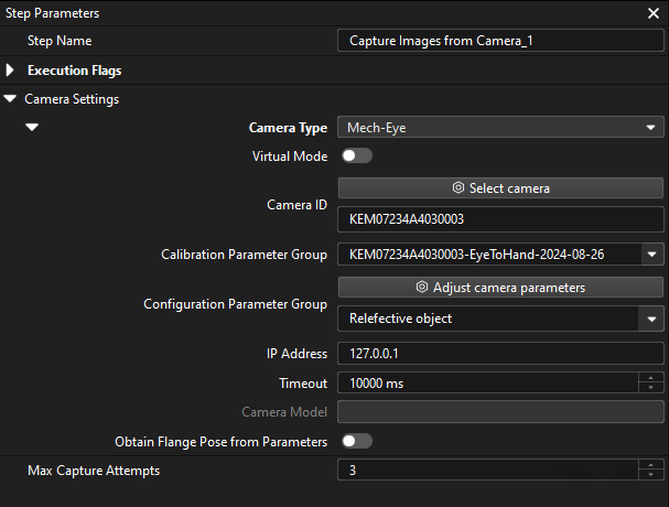
In the Graphical Programming Workspace of Mech-Vision, select the Capture Images from Camera Step, and click Select camera on the Step Parameters tab.
-
In the prompted Select camera and calibration parameter group window, click the
 icon to the right of the camera serial number. When this icon turns into an
  icon, the camera is connected successfully.
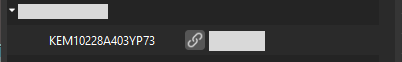
After the camera is connected, click the Select parameter group button and select the calibrated parameter group with ETH/EIH and date.
The calibration parameter group selected here is the one generated after the hand-eye calibration is completed. -
After the camera is connected and the parameter group is selected, the calibration parameter group, IP address, and ports of the camera will be obtained automatically. Make sure that Configuration parameter group is set to “Reflective object”.
-
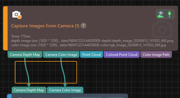
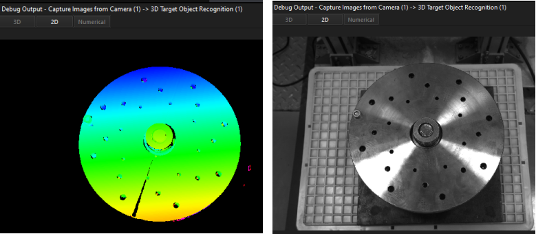
Click the Single Step Execution button of the Capture Images from Camera Step to trigger image capturing, double-click the “Camera Depth Map” and “Camera Color Image” data streams of the Step, and check whether the images were successfully captured from the camera in the Debug Output window.
-
If you can see a normal depth map and color image in the Debug Output window, the Mech-Vision software has successfully connected to the real camera and can capture images normally.
3D Target Object Recognition
Step name |
3D Target Object Recognition |
|---|---|
Phase |
Recognize Target Objects |
Illustration |
|
Description |
You need to set point cloud preprocessing parameters, make target object models in the target object editor, select the target object, set recognition parameters, and configure output ports. |
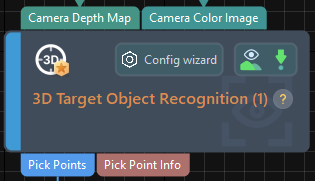
The "3D Target Object Recognition" Step provides a built-in visual "3D Target Object Recognition" tool. With the wizard, you can easily recognize target object poses in only three steps.

You can start parameter adjustment by opening the "3D Target Object Recognition" tool in either of the following ways.
-
Click the Config Wizard button on the Step block in the Graphical Programming Workspace.
-
In the Step Parameters tab, click the Config wizard button.
Point Cloud Preprocessing
Point cloud preprocessing converts the acquired image data to point clouds, detects edge point clouds, and filters out point clouds that do not meet the rules by setting valid point cloud recognition regions, thus improving subsequent recognition efficiency.
In this step, you need to set an effective recognition region to keep the interference factors out of the region to improve recognition efficiency. Please ensure that the recognition area covers the target object and extends 30 mm outward to accommodate the possible effects of incoming material deviations.
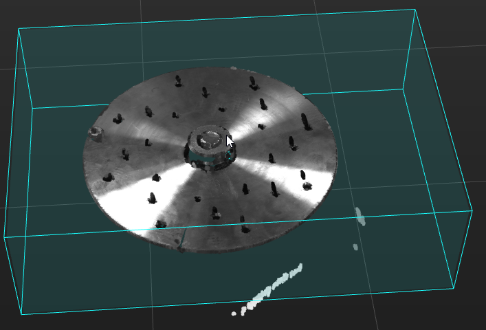
Usually, keep the default values of other preprocessing parameters. If there are many noises in the scene, you can try adjusting relevant parameters. For details, refer to Point Cloud Preprocessing.
| After parameter adjustment, you can click the Run Step button in the Preview preprocessing result area, and confirm that the preprocessing effect meets expectations in the Visualizing Space. |
Target Object Selection and Recognition
|
Make Target Object Model
In this tutorial, you will set the pick points by jogging the robot, and generate the point cloud model based on the acquired point cloud. For detailed instructions, please refer to Set the Pick Points by Jogging the Robot, and Generate the Point Cloud Model Based on the Acquired Point Cloud to make the point cloud matching model for the target object.
The target object is symmetrical, and you need to set the symmetry in the target object model.
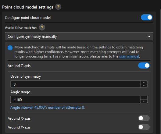
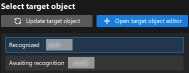
After the target object model is created, close the Target Object Editor window to return to the "3D Target Object Recognition" tool interface, and click the Update target object button. If there is only one target object model in the target object editor of the solution, the tool will automatically select the target object model. If there are multiple target object models in the target object editor of the solution, please select the target object model to use.
Set Matching Parameters
-
In the Recognize target objects area, enable the Advanced mode option.
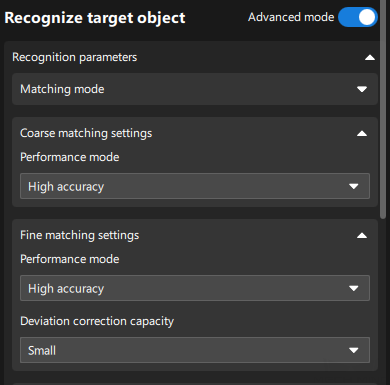
-
Set the Performance mode parameter of Coarse matching settings and Fine matching settings to "High accuracy", and the Deviation correction capacity to "Small."
-
In Adjust or Filter Poses from Coarse Matching, set the Selection Strategy to “Filter potentially false matches” and the Range to half the angle of symmetry. For example, if the angle of symmetry is 45 degrees, the range should be set to 22.5 degrees.
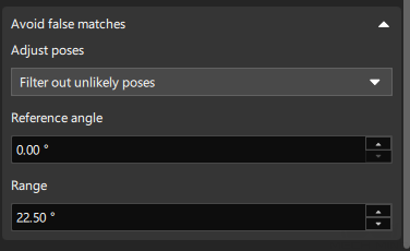
When a pick point is set by teaching, the smaller the angle difference between the output matching pose and the model pose, the higher the picking accuracy. Therefore, for symmetrical target objects, filtering out potentially false matches is essential to minimize the angle difference between the matching and template poses. -
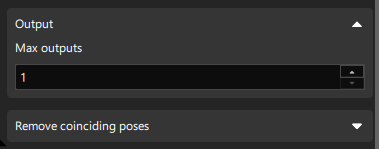
Since only one target object is recognized at a time, set Max outputs to 1.
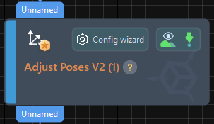
Adjust Poses V2
Step name |
Adjust Poses V2 |
|---|---|
Phase |
Adjust Poses |
Illustration |
|
Description |
Set parameters to transform poses, adjust poses, sort poses, and filter poses. |
After obtaining the target object pose, you need to adjust the pose.
With the built-in pose adjustment tool in Mech-Vision, you can easily adjust object poses and optimize the picking sequence. You can start parameter adjustment by opening the pose adjustment tool in either of the following ways.
-
Click the Config Wizard button on the Step block in the Graphical Programming Workspace.
-
In the Step Parameters tab, click the Config wizard button.
Follow these steps to adjust parameters:
-
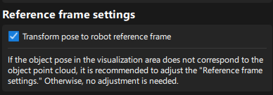
Transform poses: In the Pose adjustment tab, transform poses from the camera reference frame to the robot reference frame.
-
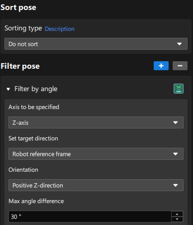
Sort poses: Since there is only one pick point, there is no need to sort poses. If there are multiple pick points on site, you can sort them according to the on-site requirements.
-
Filter poses by angle: In the Processing rules tab, filter out poses that are obviously unpickable according to their Z-axis directions.
Output
Step name |
Output |
|---|---|
Phase |
Output Target Object Poses |
Illustration |
|
Description |
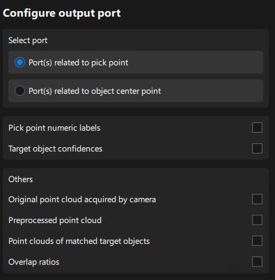
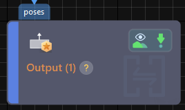
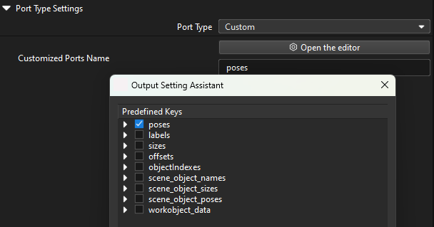
You need to switch the port to output the target object pose to the robot. |
Please set the Port Type parameter to “Custom” and select the “poses” predefined key.
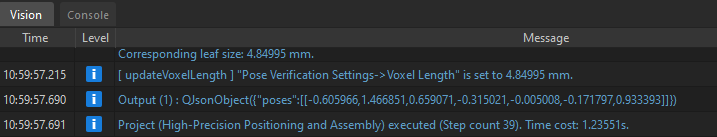
Please click the Run button to confirm that the project can run successfully and output the target object poses. You can check whether there are logs with vision results in the Vision tab of Mech-Vision’s log panel.
Now you have completed configuring the vision project.