Vision System Hardware Setup
In this tutorial, you will learn how to build the Mech-Mind Vision System.
To build the Mech-Mind Vision System, follow the procedure: Check package contents → Install hardware → Connect the network → Upgrade software (optional) → Confirm that the vision system can capture images normally.
Check Package Contents
-
Make sure that the package is intact when you receive it.
-
Check the contents against the “packing list” in the package to ensure that no devices or accessories are missing or damaged.
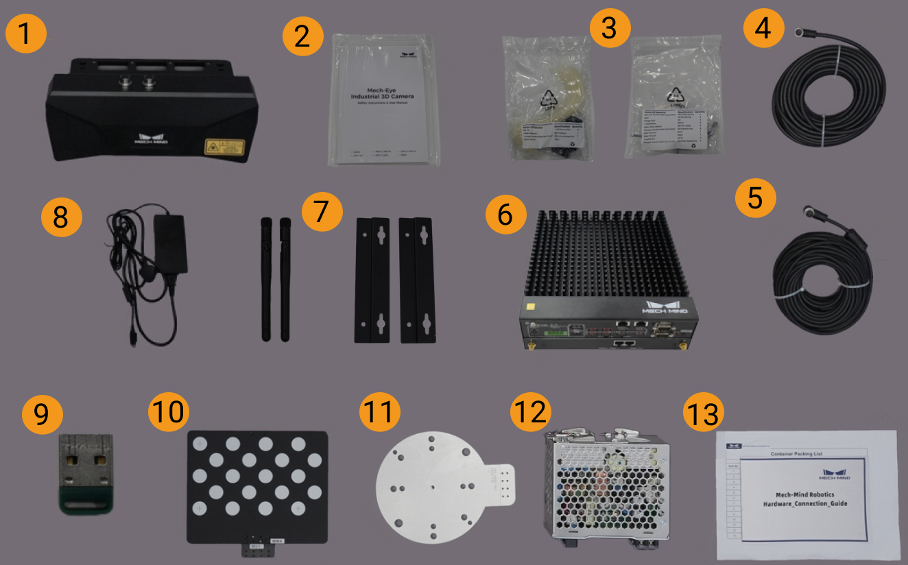
The following figure shows the devices and accessories included in a vision system shipment. The table below is for reference only. Please take the “packing list” in the package as final.
| No. | Category | Name | Function |
|---|---|---|---|
1 |
Camera and accessories |
Mech-Eye Industrial 3D Camera |
Acquires images |
2 |
Camera User Manual and Technical Specifications |
User Manual and Technical Specifications of Mech-Eye Industrial 3D Camera |
|
3 |
Camera accessory box |
Mounts the camera |
|
4 |
Camera DC power cable |
Connect the camera and the DIN rail power supply; camera power cables of different lengths can be selected according to needs |
|
5 |
Camera Ethernet cable |
Connects the camera and the IPC; camera Ethernet cables of different lengths can be selected according to needs |
|
6 |
IPC and accessories |
Mech-Mind IPC STD |
Provides the running environment for Mech-Mind software |
7 |
IPC accessories |
IPC accessories such as mounting brackets and external WiFi antennas |
|
8 |
IPC power cable and adapter |
Supplies power to IPC |
|
9 |
Project accessories |
Software licensing device (USB), also called license dongle |
Authorizes the software |
10 |
Calibration board |
Calibrates the camera |
|
11 |
Flange adapter |
Connects the calibration board to the robot flange |
|
12 |
DIN rail power supply (optional) |
Supplies power to Mech-Eye Industrial 3D Camera |
|
13 |
Packing list |
Lists all the devices and accessories in the package |
|
|
Contact Mech-Mind if any items are missing or damaged. |
Prepare Other Materials
In this tutorial, besides the items in the package, you still need to prepare the materials shown in the following table by yourself.
| Item | Function |
|---|---|
Monitor |
Provides display for the IPC |
HDMI cable |
Connects the monitor and the IPC |
RJ45 Ethernet cable |
Connects the IPC and the robot controller |
| In this tutorial, the IPC and robot controller are directly connected through an RJ45-to-RJ45 Ethernet cable, and the IPC and the camera are directly connected through the camera Ethernet cable. Alternatively, you can use a router to connect the IPC and the robot controller, and the IPC and the camera, which is not covered in this topic. |
Install Hardware
Mounts the camera
|
In this tutorial, the camera is mounted on the camera mounting frame (that is the eye to hand (ETH) mounting mode). In addition, the camera can also be mounted onto the end terminal of the robot (that is the eye in hand (EIH) mounting mode). |
-
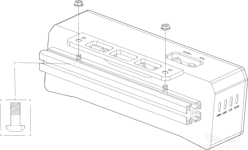
Get the camera mounting bolts and wrench from the camera accessory box.
-
Tighten the two bolts with the wrench as shown below.
-
Please remove the lens protection film after mounting the camera.
-
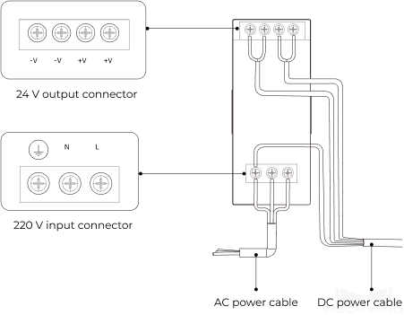
Power the camera with the DIN rail power supply.
-
Connect the DC power cable:
-
Connect the +V wire to the +V connectors of the 24 V output connectors;
-
Connect the -V wire to the -V connectors of the 24 V output connectors;
-
Connect the PE wire to the 220 V input connector
 .
.
-
-
-
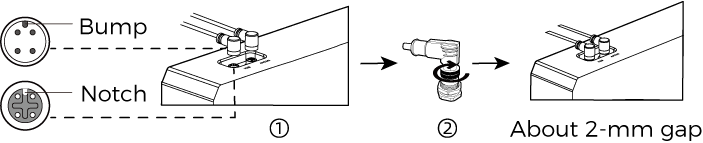
Install the Ethernet cable of the camera.
Make sure the bump of the M12 connector and the notch of the ETH port, and tighten the nut after plugging in the cable.
Mount the IPC
|
The IPC is normally mounted in the control cabinet. The environment in which the IPC is mounted requires good heat dissipation, ventilation, and dust-proof. It should be mounted at a location where Ethernet cables, HDMI cables, and USB ports can be easily mounted and maintained. |
To mount the IPC, follow these steps:
-
Prepare the wrench, bolts, nuts, and gaskets that are not included in the package beforehand.
-
If the robot controller is designed with mounting holes for the IPC in it, secure the IPC in the controller: place the bolt, gasket, and nut one by one, and tighten the two bolts with a wrench, as shown below.
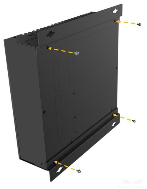
If the location of the robot controller is already fixed, skip this step and just place the IPC inside the controller.
-
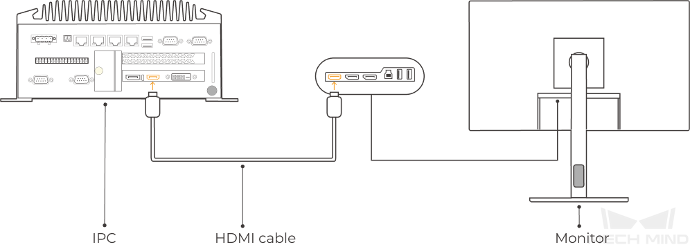
Connect the IPC and the monitor with the HDMI cable.
Plug one end of the HDMI cable into the HDMI port of the monitor, and the other end into the HDMI port of the IPC, as shown below.
-
Connect the IPC to the power supply unit with the power adaptor.
Plug the power cable of the power adaptor into the power connector of the IPC. Connect the adaptor to the power supply on the other end.
-
Insert the license dongle.
Plug the license dongle into a USB port of the IPC.
-
After the IPC is connected to the power supply, switch on the IPC.
-
If the IPC is started normally, the power indicator should be solid on.
-
If the IPC cannot be started, contact Mech-Mind Technical Support.
-
Connect the Network
In this section, you will learn how to connect the network between the IPC and the camera, and between the IPC and the robot.
In the following sections, the following IP addresses will be used for network settings. Please adjust the network settings according to your actual network environment.
| Device | IP Address | |
|---|---|---|
IPC |
Ethernet port connecting to the camera |
192.168.100.10 |
Ethernet port connecting to the robot controller |
192.168.200.10 |
|
Camera |
192.168.100.20 |
|
Robot |
192.168.200.20 (already set on the robot) |
|
Connect the IPC and the Camera, and the IPC and the Robot Controller
-
Plug the other end of the Ethernet cable connected to the camera into an Ethernet port of the IPC.
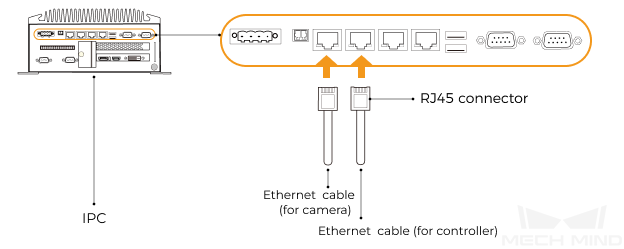
-
Use an RJ45-to-RJ45 Ethernet cable to plug one end into the Ethernet port of the robot controller and the other end into an Ethernet port of the IPC.
Set the IP Addresses on the IPC
-
Select on the IPC. The Network Connections page will be displayed.
-
Right-click the Ethernet port connected to the camera, and select Rename to rename the Ethernet port, such as “To_camera”.
-
Right-click the Ethernet port connected to the camera, and select Properties to enter the Ethernet Properties page.
-
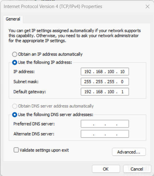
Select the Internet Protocol Version 4 (TCP/IPv4) checkbox, and then click the Property button to enter the Internet Protocol Version 4 (TCP/IPv4) Properties page.
-
Select the Use the following IP address radio button, set the IP address to “192.168.100.10”, Subnet mask to “255.255.255.0”, and Default gateway to “192.168.100.1”, and then click the OK button.
-
Repeat steps 2 to 5 to rename the Ethernet port connected to the robot controller (for example, “To_robot”), and set the IP address for this Ethernet port. For example, the IP address of this Ethernet port is “192.168.200.10”.
The IP address of the robot and that of the IPC Ethernet port connected to the robot controller must be on the same subnet.
Set the Camera IP Address
-
Double-click
 on the desktop of the IPC to open and run Mech-Eye Viewer.
 -
Select the camera in the camera list, and hover the cursor on the camera. Click
 to open the IP Configuration dialog box.
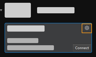
If the camera cannot be found or connected, please refer to Camera Troubleshooting.
-
In IP Configuration area, select the Set as Static IP radio button, and set the IP Address Class, IP Address, and Subnet Mask according to the actual network environment. For example, in the following figure, the above parameters are set to “Type C 192.168.x.x”, “192.168.20.116” and “255.255.255.0”. Then click the Apply button.
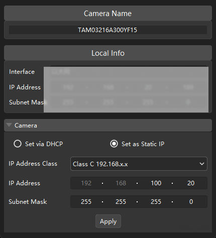
|
The IP address of the camera and that of the IPC Ethernet port connected to the camera must be on the same subnet. |
Test the Network Connectivity
-
Press Win + R to open the Run dialog box.
-
Type
cmdin the Run dialog box, and then click OK. -
Type ping XXX.XXX.XX.XX in the command prompt window and press Enter to execute the command.
Replace XXX.XXX.XX.XX with the actual IP address of the camera/robot.
If the network connectivity is normal, you should receive the following response:
Pinging XXX.XXX.XX.XX with 32 bytes of data:
Reply from XXX.XXX.XX.XX: bytes=32 time<1ms TTL=128
Reply from XXX.XXX.XX.XX: bytes=32 time<1ms TTL=128
Reply from XXX.XXX.XX.XX: bytes=32 time<1ms TTL=128
Reply from XXX.XXX.XX.XX: bytes=32 time<1ms TTL=128
Upgrade the Software (Optional)
The IPC purchased from Mech-Mind already has the latest version of Mech-Mind software installed.
Please check if all software on the IPC is running with the latest version. If so, skip this section; if not, follow the sections below to update the software to the latest versions.
Confirm the Quality of Acquired Images
Confirm that the vision system can acquire images normally and that the image quality meets the requirements after verifying the network connectivity between the IPC and the camera, and the IPC and robot, and confirming that the software runs the latest version.
-
Place the target objects at the center of the working plane within the camera’s field of view.
-
Open and start Mech-Eye Viewer by double-clicking
on the desktop of the IPC. -
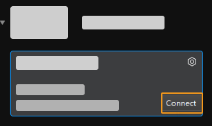
Select the camera in the camera list and click Connect.
-
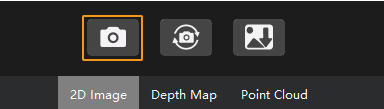
After selecting the parameter group template “Threaded rod,” click the “Acquire once” button.
-
Make sure that the target objects on the edge and on the top layer are all within the camera’s field of view.
-
Make sure that the acquired images meet the following standards. The qualified images are as follows:
-
2D image: The acquired 2D image is not significantly overexposed (too white to recognize objects) or underexposed (too dark to recognize object details).
-
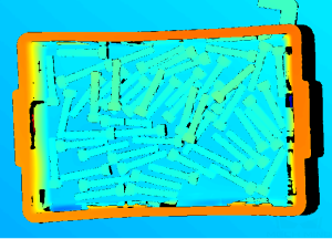
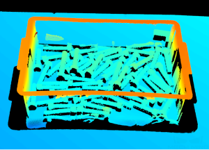
Depth map and point cloud: All relevant parts of the object can be recognized.
2D image Depth map Point cloud 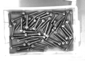
-
|
If the acquired images do not meet the required standards, use Mech-Eye Viewer to adjust camera parameters. |
Up to now, you have learned how to build the vision system.
Capture Images and Train Deep Learning Models
When the quality of the on-site target object’s point cloud is poor or the scene point cloud is prone to incorrect recognition, deep learning will be used to assist in recognizing target object poses.
| This case provides a deep learning model trained in advance. You can download it by clicking here. If you need to train your own deep learning model, refer to this section to acquire images and train a deep learning model. |
-
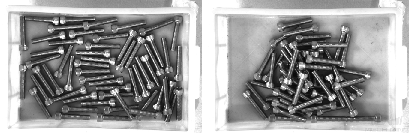
Capture images according to the following rules.
-
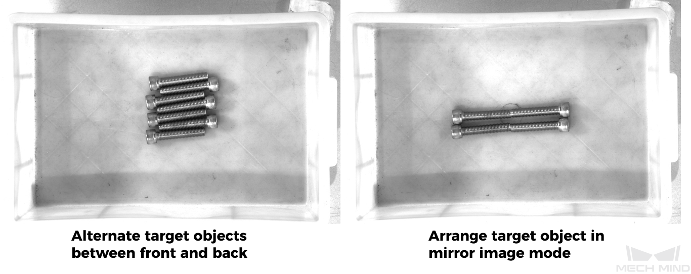
Capture images under normal conditions,where objects are stacked in a scattered manner and in a concentrated manner.
The number of target objects is gradually reduced from a large number. Each time, remove one or more target objects, as appropriate, and then reorganize the order and capture again until all target objects have been removed.
-
Capture images under special conditions, such as when multiple objects are stitched or stacked.
If multiple target objects are stitched or overlapped indistinguishably, you need to increase the number of captured images (about ten).
-
-
Refer to Train High Quality Models to train a high-quality instance segmentation model.