Tools
This section introduces tools and corresponding configurations.
Introduction
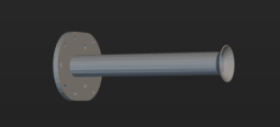
Tools, such as grippers and suction cups, are mechanical devices attached to the end of the robotic arm to perform various tasks.
Model of the Tool
In order to visualize the tool in the 3D simulation area and make the tool involve the collision detection, you need to create a visualization model and a collision model of the tool and import them to the model library.
The following table shows the formats of the supported visualization model and collision model of the tool.
| Format | STL | OBJ | DAE | Binvox |
|---|---|---|---|---|
Visualization Model |
√ |
√ |
√ |
× |
Collision Model |
√ |
√ |
× |
× |
|
Type of the Tool
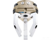
Mech-Viz supports the regular tool, depalletizing vacuum gripper, and array gripper.
| Type of the Tool | Description | Illustration |
|---|---|---|
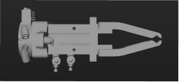
Regular Tool |
All tools except suction cups used for depalletizing and array grippers. For example, the pneumatic gripper and single suction cup. |
|
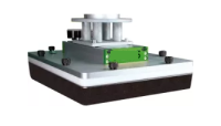
Depalletizing Vacuum Gripper |
Rectangular suction cups used for depalletizing. Multi-block suction cups are supported. |
|
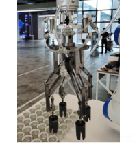
Array Gripper |
An array of tools at the end of the robot that can be used to perform pick-or-place tasks concertedly. |
|
Rotational Symmetry
A rotational symmetric tool will coincide with itself after rotating around its axis of symmetry. Configuring the symmetry of the tool can prevent the end of the robot from rotating meaninglessly when picking and placing, and therefore increase the picking success rate and reduce the planning time consumption. Therefore, the robot can move more smoothly and swiftly.
No Rotational Symmetry |
|
180° Rotational Symmetry |
|
Rotational Symmetry at Any Angle (Circular) |
|
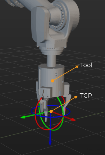
Tool Center Point (TCP)
The tool is used to pick and place the object. When you move the robot to a specified point to perform pick-or-place task, you are actually moving the TCP (Tool Center Point) to that point. The default TCP is located at the end of the robot, but sometimes you need to adjust the TCP to ensure that the TCP is at the right place for the actual pick-and-place process.
Configure the Tool
Import the Collision Model and Visualization Model
Click the + next to , and select the collision model and visualization model in the pop-up window, and then click Open.
| When entering the tool configuration window, you can add a model by selecting Import new model in the drop-down menu of Collision model and Visualization model. |
Add the Tool
Go to and click + to open the Tool Configuration window.
-
Enter a Tool name.
-
Select the Tool type according to the actual situation.
-
Select the Collision model in the drop-down list.
-
Select the Visualization model for visualization in the 3D simulation area. When the position or size of the visualization model is not correct, please refer to Adjust the Position or Size of the Tool Model to adjust the model.
-
Set the Rotational symmetry to None or Symmetrical according to the actual situation. If you select Symmetrical, you also need to set the Order of symmetry parameter.
-
Follow either of the methods below to set the TCP.
Update TCP from robot
Click the button to synchronize the TCP of real robot to the software.
Perform TCP calibration
Control the robot to rotate around a fixed point and record multiple sets of flange poses to calculate the TCP.
Modify the TCP parameter
Modify the Euler angles or quaternion directly.
Use precise TCP data
If you have already obtained the accurate TCP data by other methods, you can click Edit pose and paste the data in the pop-up window.
-
If you are using a regular tool, you do not need to configure the control logic. If you are using a vacuum gripper or array gripper, please refer to Configure the Control Logic of the Tool to continue to configure the control logic.
-
Click OK in the end.
If you need to add more tools, please repeat the above steps.
Delete the Tool
Follow either of the following steps to delete the tool.
-
Go to , select the tool name and press the Delete key.
-
Go to , right-click the tool name and select 删除 in the context menu.
Modify the Tool
-
Follow either of the following steps to open the Tool Configuration window.
-
Go to , double-click the tool name.
-
Go to , right-click the tool name and select Tool Configuration in the context menu.
-
-
Modify the parameters according to the actual requirement.
-
Click OK.
Set as Active Tool
If you only add one tool, the current tool is the active tool. If you add multiple tools, the first added tool will be used as the active tool by default.
To set a tool as active tool, go to , right-click the tool you want to use and select Set as Active Tool.
Adjust the Position or Size of the Tool Model
Follow the steps below to adjust the tool model when its position is not correct.
-
Double-click the tool model under .
-
Adjust the pose parameters in the pop-up Edit Model Transform window to adjust the model’s position in the 3D simulation area.
Follow the steps below to adjust the model when its size is not correct.
-
Double-click the tool model under .
-
In the pop-up Edit Model Transform window:
-
Adjust the Scale if you want to adjust the scale of the entire model.
-
If you want to adjust the scale on the individual X, Y, or Z direction, clear the Keep ratio for X,Y,Z checkbox, and adjust the scale on each direction respectively.
-
Configure the Control Logic of the Tool
Regular Tool |
Please refer to Configure Control Logic for Regular Tool for detailed instructions. |
Depalletizing vacuum gripper |
Please refer to Depalletizing Vacuum Gripper for detailed instructions. |
Array gripper |
Please refer to Array Gripper Configurator for detailed instructions. |