Path Planning
Function
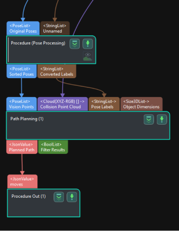
This Step uses the input vision points to plan the robot path and outputs the successfully planned robot path.
|
Usage Scenario
This Step is usually used in projects where the Standard Interface or Adapter is used for communication, and only the robot motion path near the vision point needs to be planned. After you build a scene and input the vision points, this Step will output a collision-free robot motion path after point cloud collision detection and path planning.
The common predecessors and successor of this Step are as follows:
-
Predecessors: Steps related to pose adjustment and pose processing.
-
Successor: the Procedure Out Step (used to output the successfully planned robot path).

Input and Output
Input
-
Vision Points: Poses input to this port will be used for robot path planning.
-
Collision Point Cloud: Point clouds input to this port will be used for collision detection with the tool.
-
Pose Labels: Object labels corresponding to vision points will be input to this port.
-
Object Dimensions: Object dimensions corresponding to vision points will be input to this port.
The following three input ports will appear after the Update Scene Object Settings is enabled.
-
Scene Object Names: The names of the scene objects will be input through this port.
-
Scene Object Dimensions: The dimensions of the scene objects will be input through this port.
-
Scene Object Poses: The poses of the scene objects will be input through this port.
Parameter Description
Path Planning Settings
Workflow Configuration
Description: Open the path planning tool and select the workflow created with the path planning tool in the drop-down list.
Update Scene Object Settings
This feature is usually used in scenarios where the bin pose should be updated dynamically. To ensure its proper functioning, you should enable Update bin pose with vision under Global configuration in the path planning tool.
Once this option is switched on, Scene Object Names, Scene Object Dimensions, and Scene Object Poses input ports will be added to the Step.