How to update bin pose in Mech-Viz?
| First, please make sure to add a bin to Scene objects in the project resource tree. Choose Bin as the Scene model, and input the actual dimensions and thickness of the bin. |
The bin pose can be updated dynamically with the following two methods.
Method 1: Use the “Update Bin Pose with Vision” feature in the “Vision Move” Step
-
In the parameter panel of the Vision Move Step, go to Supplementary Features > Re-Locate Bin with Vision and select Update Bin Pose with Vision.
-
In Mech-Vision, open the vision project for bin recognition, and set parameters in the Procedure Out Step.
-
Select Custom as Port Type.
-
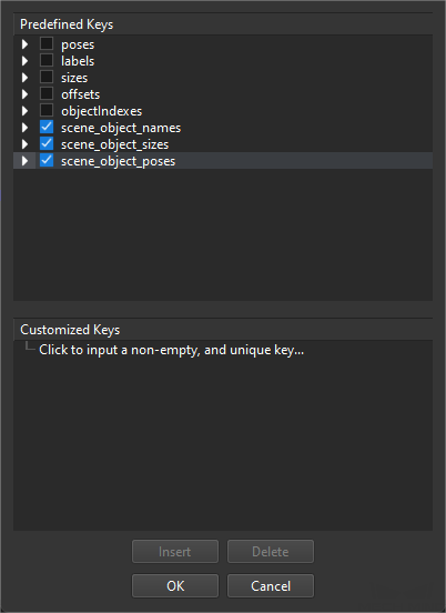
Click Open the editor, and select scene_object_names, scene_object_sizes, and scene_object_poses. The three keys correspond to the name, size, and pose of the scene object in Mech-Viz. After selecting scene_object_names, scene_object_sizes and scene_object_poses can be selected as needed. If only scene_object_names is selected, the Update Scene Objects Step will run along the Failure exit port.
-
Click OK in the window.
-
Method 2: Use the “Update Scene Objects” Step
|
-
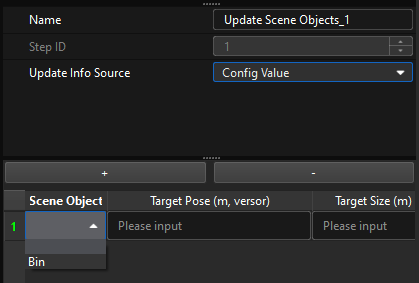
If Update Info Source is set to Config Value in the Update Scene Objects Step, the pose and dimensions of the bin will be updated to the user-defined Target Pose and Target Size.
Click +, and select the bin to be updated in the Scene Object. Then, input the Target Pose and Target Size. The format of target pose should be X, Y, Z (m) plus quaternions, and the target size is the dimensions in X, Y, and Z-directions in meters.
-
If Update Info Source is set to Vision Service in the Update Scene Objects Step, the bin pose will be updated according to the recognition results in the specified Mech-Vision projects.
-
In Mech-Viz, in the Vision Service Name parameter of the Update Scene Objects Step, select the vision project for bin recognition.
-
In Mech-Vision, open the vision project for bin recognition, and set parameters in the Procedure Out Step.
-
Select Custom as Port Type.
-
Click Open the editor, and select scene_object_names, scene_object_sizes, and scene_object_poses. The three keys correspond to the name, size, and pose of the scene object in Mech-Viz. After selecting scene_object_names, scene_object_sizes and scene_object_poses can be selected as needed. If only scene_object_names is selected, the Update Scene Objects Step will run along the Failure exit port.
-
Click OK in the window.
-
-
Suggestions
-
If the bin pose might change with each pick-up, it is recommended to use the “Update Bin Pose with Vision” feature in the Vision Move Step (namely Method 1) to dynamically update the bin pose before picking.
-
If the bin pose only needs to be updated once, it is recommended to use the Update Scene Objects Step (namely Method 2). For example, if the bin is located before picking and does not move during the process of picking, there is no need to update the bin pose before each pick-up. If multiple dimensions of bins are used on-site, a separate vision project for bin recognition can be created using Method 2, thus making project logic for recognizing target objects simpler and the recognition efficiency higher.
-
The pose of the bin-type scene objects created in Mech-Viz is located at the geometric center of the bin (i.e., inside the bin). However, in Mech-Vision, the pose of the bin is usually calculated based on the detected shape of the upper opening surface of the bin. The calculated pose is located at the geometric center point of the upper surface of the bin. At this point, if you need to use the Procedure Out Step in Mech-Vision to send the bin pose to Mech-Viz for updating, you usually need to first use the Translate Poses along Given DirectionStep to adjust the pose of the bin’s upper surface to the geometric center of the entire bin.
-
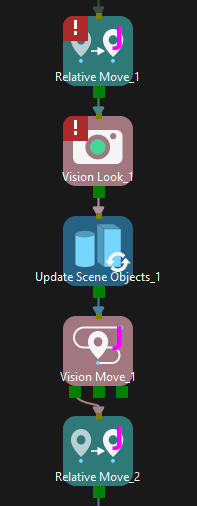
When obtaining the bin pose from Vision Service in the Update Scene Objects Step, the vision service should be called in the Vision Look Step. At this time, if the same Mech-Vision project is used to recognize both the bin and the target object, and there are no other Vision Look Steps between the Update Scene Objects Step and the Vision Move Step (as shown below), then the Update Scene Objects Step will consume the vision results, causing an error in the subsequent Vision Move Step due to the lack of available vision results.