Path Planning Tool
| The usage and some of parameters of the path planning tool differs from that of Mech-Viz. To avoid confusion between the two, please refer to their respective manual when using the tools/software. |
This section introduces the path planning tool and how to use it.
Function
The path planning tool is used to plan a collision-free motion path near the workobject for the robot.
The robot motion path is essentially the motion path of the TCP when the robot completes a task. When the robot moves, the tool may collide with the workobject or scene object. Therefore, to provide various resources and data required for the collision detection and path planning, you need to build a scene that is close to the real scenario, configure the robot tool, and input the vision points and scene point cloud. With the path planning tool, you can input these resources and data to enable the collision detection and path planning. The planned path will be output via the “Path Planning” Step, and therefore the robot can be guided to complete tasks such as picking.
Introduction to Interface
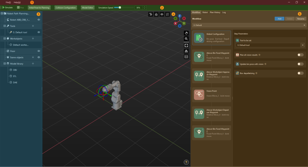
The interface of the path planning tool, as shown below, consists of five parts.

For resetting the settings, saving the settings, and exiting the path planning tool. |
|
For project simulation, setting the initial robot pose, collision detection, and opening the model editor. |
|
For managing the resources used in the project, including tools, workobjects (i.e., the target objects to be picked or processed), and scene objects. |
|
The area where the robot motion path, vision poses, point cloud, etc., are visualized during the simulation. |
|
For configuring the workflow and robot pose and checking the plan history and log. |
Basic Procedures
Before using the path planning tool, please connect the input and output ports of the Path Planning Step with others according to the port type.
After you connect the Steps properly, click Open the editor in the Step Parameters panel of the Path Planning Step, select the robot model according to the actual robot model in use in the Robot Model Library window, and then you can enter the interface of the path planning tool.
The basic procedures for using the path planning tool are as follows. Click the link below to get started with the path planning tool.
Configure the resources required in the project, including tools, workobjects, scene objects, etc. |
|
Create the robot motion control program in the form of a flowchart. |
|
Detect possible collisions as the robot moves along the path. |
|
Run and debug the project by using a simulated robot. |