User Manual
Quick Guide
Safety and Maintenance
Before installing, operating, and maintaining this camera, please read and observe the following precautions:
-
This camera should be used in an environment that meets the design specifications; otherwise, malfunctions may occur. Any functional abnormalities or damage caused by failure to follow the relevant provisions are not covered by the warranty.
-
Mech-Mind assumes no responsibility for damage, injury, or any legal liability resulting from improper or incorrect operation of this product.
Safety Precautions
-
If you find damage, missing parts, or water ingress in the product or accessories upon unboxing, do not install or use it; contact Mech-Mind promptly for assistance.
-
Avoid transporting and using the device in environments with direct sunlight or splashing rain.
-
Avoid using it in strong electric fields, strong magnetic fields, or environments with strong vibration; ground the camera during installation.
-
Avoid using it in high-dust environments. The electrical interfaces of this camera are not dust-proof, and heavy dust can affect imaging.
-
Avoid large heat sources nearby, and use the device in a well-ventilated place without direct sunlight.
-
External I/O trigger signals must meet the device requirements; otherwise, the camera may be damaged.
-
Ensure the power is disconnected during cabling. Do not plug or unplug connectors when circuits are live, and do not operate under power to avoid equipment damage and the risk of electric shock.
-
If the external power adapter is damaged, do not replace it yourself. Contact Mech-Mind promptly for a replacement.
-
Do not look directly at the device light source when the device flashes; doing so may impair the observer’s vision.
Precautions for Preventing Electromagnetic Interference and Static Accumulation
-
Ensure the camera housing is grounded to prevent static buildup.
-
Ensure the I/O trigger wire and the power wire share a common ground to ensure proper triggering.
-
Do not route cables in parallel with other high-power equipment. If unavoidable, be sure to shield the cables.
Cleaning and Maintenance
Camera Body Cleaning
Clean the housing in an indoor environment free of heavy dust. Proceed as follows:
-
Disconnect the camera power.
-
Wipe the body with a lint-free cloth and a neutral cleaner. Make sure the cloth is wrung out and not dripping, and avoid touching the camera lens while wiping.
-
After wiping, allow any residual moisture to evaporate naturally.
-
Reconnect the power.
|
Always disconnect the power before cleaning. |
Camera Lens Cleaning
The camera lens surface is susceptible to contamination and requires a high level of cleanliness. Clean it strictly as instructed to avoid lens damage. The cleaning methods are as follows:
-
Air blowing
When only a small amount of dust is present, use an air blower to blow dust off the lens surface; a simple handheld blower can be used.
Do not blow with your mouth to avoid secondary contamination.
-
Lens brush cleaning
When only a small amount of dust is present and the air blower cannot remove it, gently sweep the dust off the lens with a lens brush.
Do not use your hands to remove dust from the lens to avoid secondary contamination.
-
Contact cleaning
For stubborn stains on the lens surface, such as liquid residue or adhesive residue, wipe with degreased cotton, a lint-free cloth, or lens tissue moistened with high-concentration alcohol.
Do not use water or other liquids to wipe, in order to avoid secondary contamination.
Create and Run a Model Quickly
Connect the Hardware
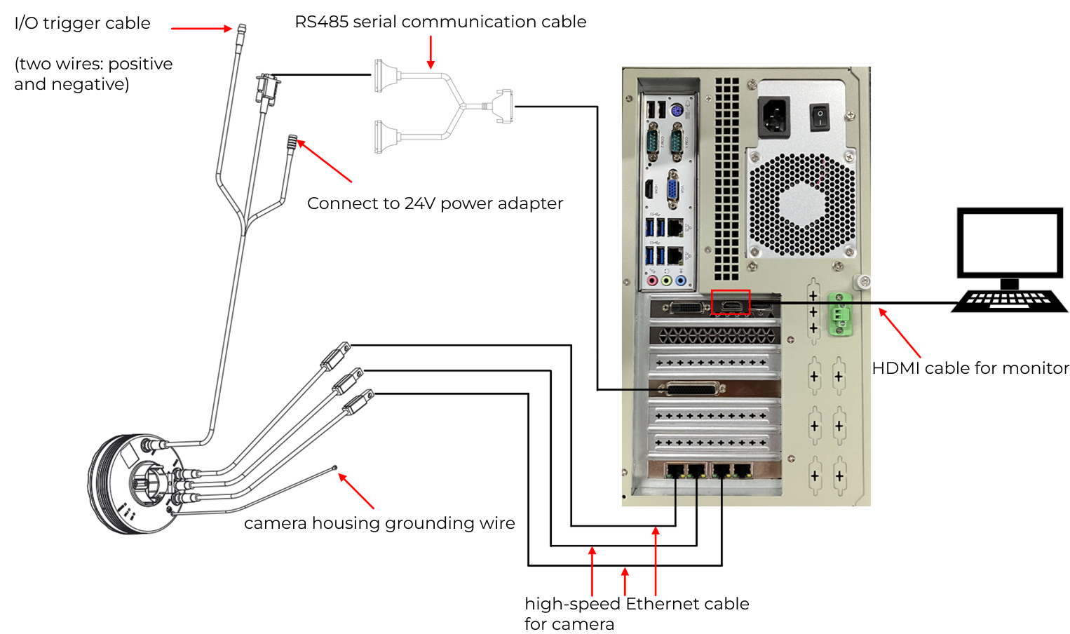
Complete the wiring according to the illustrated connection rules. When power is supplied normally, it is not necessary to connect the Mech-GlueCheck software. When the trigger line is pulled high to a high level, the camera’s LED indicator will light up.
|
The monitor should be connected via an HDMI cable to the HDMI video output port on the discrete graphics card. |
Configure the Camera
Configure the camera IP in the software according to Camera configuration.
Interface with the Robot Protocol

According to the communication protocol in Communication and protocol settings, send the segment start and end commands during the gluing process. After gluing starts, the system will enable control I/O signals. Once the I/O signals are enabled, the camera will illuminate even if the software is not running.
Run the robot repeatedly to check whether the camera lights up and turns off as required.
Acquire Images and Build a Model
-
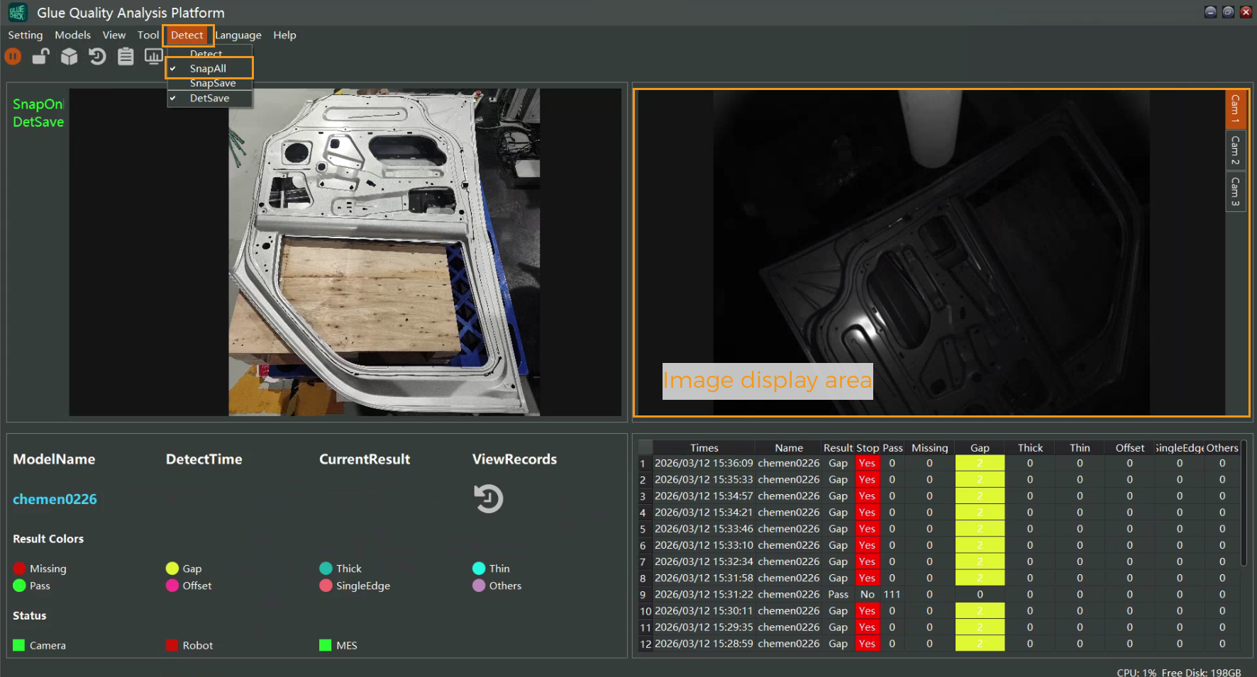
Switch to the Live view mode to check whether the camera is capturing images correctly. If acquisition is abnormal, check the camera connections and the camera configuration in the software.
-
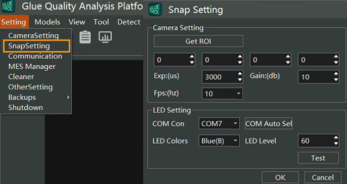
Switch to the Live save mode, set the camera exposure and LED color so that the acquired images have good contrast. Acquire and save complete images.
-
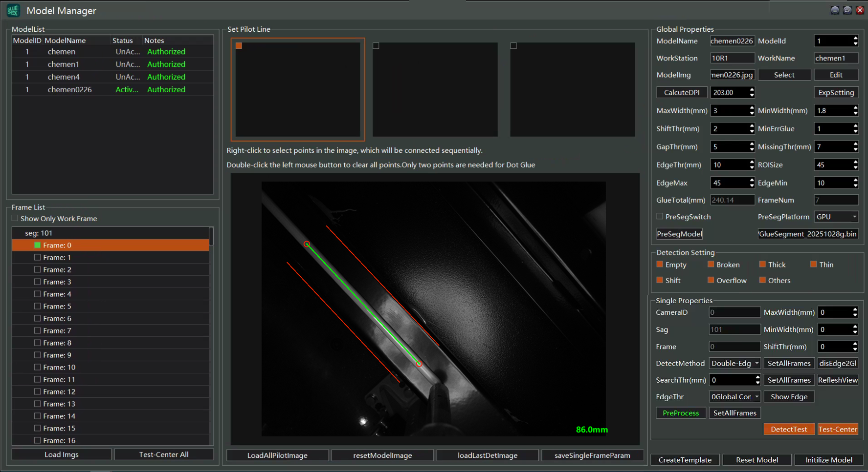
Import the images saved in real time, and select appropriate frames to add guide lines. You can add guide lines to a few frames first, then modify the remaining frames.
-
Set the model name and model ID. The model ID must be consistent with that used when importing the images.
-
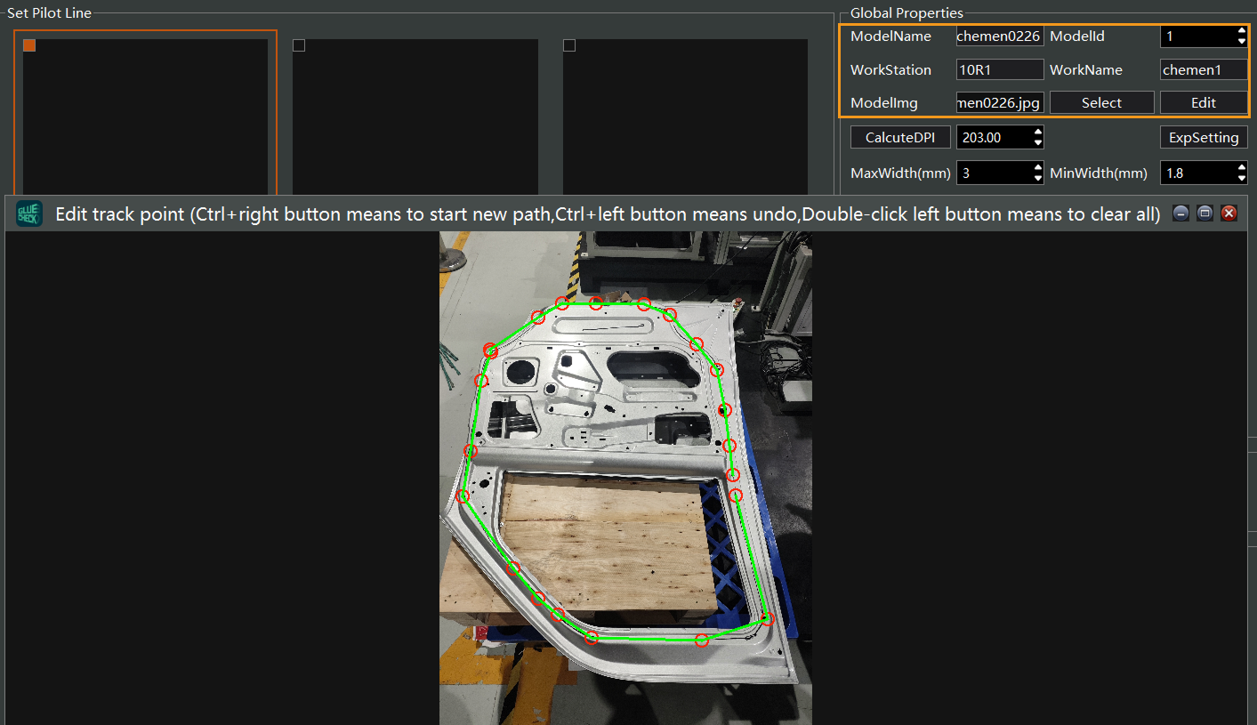
Select the workpiece image and draw the gluing path(s). The number of gluing paths should match the number of imported gluing image groups.
-
Click Build model and wait for the model to be generated successfully.
Product Introduction
Use Cases
Mech-Eye Glue Detection Camera consists of three 2D cameras, enabling 360° full-view bead inspection, and can dynamically and in real time monitor bead quality, thereby effectively improving production quality.The system conducts real-time inspection of the bead and simultaneously displays the inspection results, and once dispensing is completed it can detect quality defects such as bead breaks, overflow, beads that are too wide or too narrow, and positional deviation, and it provides real-time alarms. Inspection data are stored automatically for subsequent issue traceability and statistical analysis.
Body-in-white bead application is an important process in automobile manufacturing, which can improve the vehicle’s sealing and waterproof performance and NVH performance, and it plays an important role in vehicle lightweighting and energy efficiency. As automotive manufacturing processes continue to advance, the types, performance, and process specifications of body bead application are continuously optimized, and dispensing equipment is constantly being upgraded.In applications such as automotive battery assembly where higher bead quality is required, Mech-Eye Glue Detection Camera can increase the detection rate of defective products and effectively improve bead quality.
Features
-
Supports real-time bead inspection, with inspection speed up to 1500 mm/s, in high-contrast scenes the inspection coverage can exceed 99%.
-
Supports multiple light source color adjustments, adaptable to different bead colors and background environments.
-
Supports detection of multiple defect types including missing bead, bead break, irregular bead (too wide or too narrow), misaligned bead, and overflow.
-
Supports fast querying and report export.
-
Supports a variety of dispensing gun brands, including Daming, Nordson, SCA (Atlas Copco), Dürr, Intec, and GRACO.
Working Principle
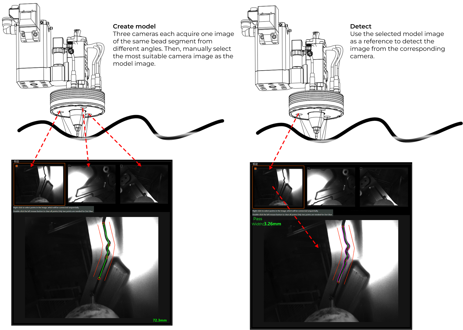
The camera operation is mainly divided into two stages:Model creation and Real-time detection.
-
Model creation stage
Three cameras simultaneously capture images of the workpiece from different angles. In this stage, for each frame a suitable and unique camera image is selected as the model, and during real-time inspection that camera image and the model data are used for detection. Because the capture frame rate must be higher than the motion speed, the bead segments captured in consecutive frames may have substantial overlap, so model frames can be selected at intervals of one or more frames.
-
Real-time detection stage
During real-time detection, the robot’s motion path and speed cadence need to remain consistent with the model creation stage (minor differences in bead position are allowed). Real-time inspection directly uses the model image and data corresponding to the inspection frame for fast detection. After each frame is processed, the system aggregates the results and ultimately outputs the inspection result for the entire part.
Typical Detectable Bead Types
| Bead Type | Description | Illustration |
|---|---|---|
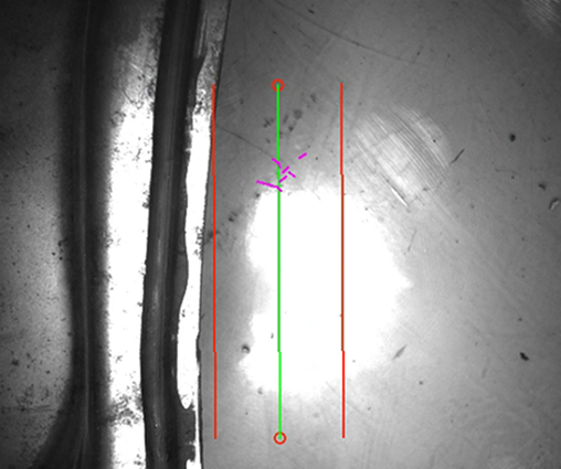
Missing bead |
Complete absence of bead, or a break length exceeding the specified threshold. |
|
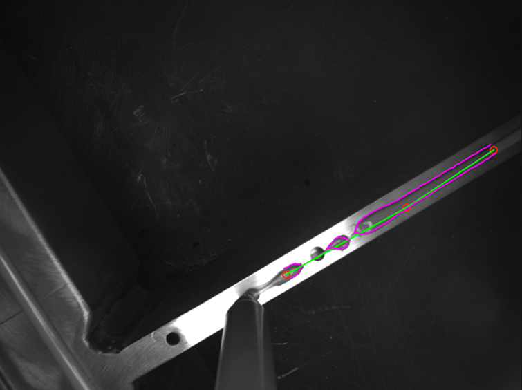
Bead break |
Undetected bead length exceeds the specified threshold. |
|
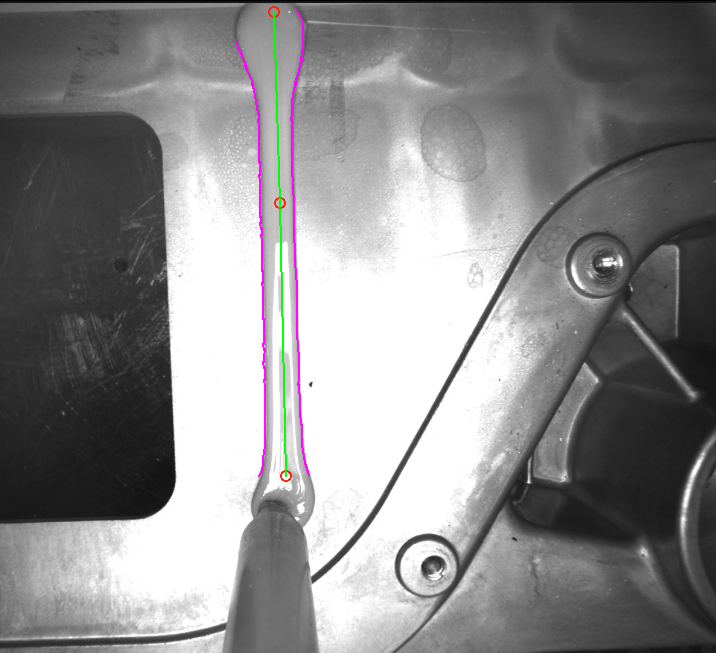
Too wide |
Detected bead width exceeds the specified threshold. The bead width is closely related to the DPI parameter in the model. |
|
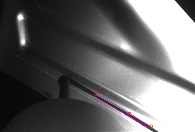
Too narrow |
Detected bead width is below the specified threshold. The bead width is closely related to the DPI parameter in the model. |
|
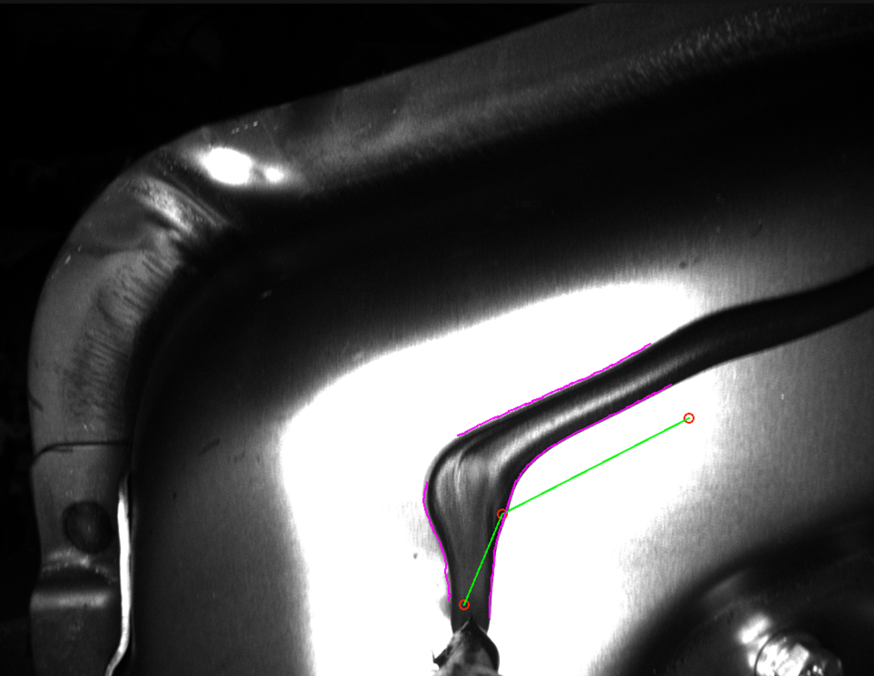
Misaligned bead |
The detected bead position deviates from the model’s guide line by more than the specified threshold, and excessive deviation may cause detection failure and be misclassified as missing bead or bead break. |
|
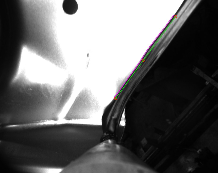
Overflow |
The bead overlaps the edge of the workpiece, resulting in only one side of the bead being detectable. |
|
Hardware Introduction
Camera Appearance and Interfaces
Mech-Eye Glue Detection Camera provides three independent Gigabit Ethernet ports and comes with a power and I/O communication interface. An independent grounding terminal is provided on the back of the camera for reliable grounding.
The camera has a ring-shaped structure with an outer diameter of 152 mm, an inner diameter (glue gun hole diameter) of 44 mm, and a thickness of 51 mm (excluding connector protrusions).
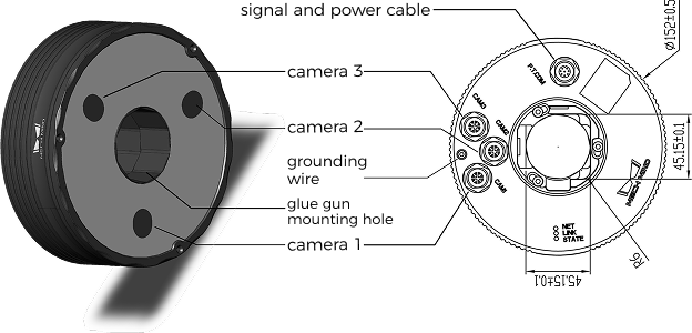
| Interface | Dimensions and Model | Purpose and Description |
|---|---|---|
Glue gun hole |
44 mm diameter |
Allows the glue gun to pass through the camera and be secured to it via a camera adapter. |
Network port |
X-coded M12 high-speed network connector (8-pin) |
Used to transmit camera image acquisition data; requires a Gigabit Ethernet cable. |
Power and I/O communication interface |
A-coded M12 connector (8-pin) |
Used for power supply and signal communication; includes the power interface, I/O trigger interface, and an RS-485 communication serial port. |
Grounding interface |
- |
Used to ground the camera housing; generally shares a common ground with the on-site robot. |
The dimensions of the camera are shown below.

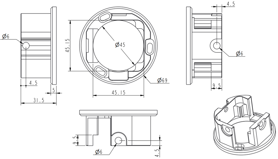
The dimensions of the camera adapter for securing the camera to the glue gun are shown below.
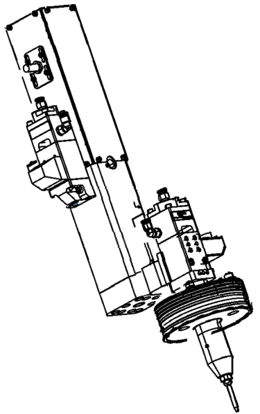
The camera mounting method is shown below.
Cables and Connections
Mech-Eye Glue Detection Camera connects to the IPC via three standard X-coded M12 high-speed Ethernet connections and communicates with the inspection software via the RS-485 interface. The I/O trigger line connects to the robot to control the camera’s image capture, and the 24V power cable supplies power to the camera.
|
The monitor should be connected via an HDMI cable to the HDMI video output on the discrete graphics card. |
LED Status Indicators

| LED indicator status | Camera status |
|---|---|
Power indicator steady on |
Camera power is supplied normally. |
Power indicator off |
Camera power is off. |
IPC-related Configuration and Precautions
-
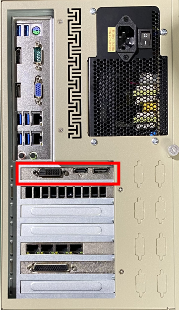
The display should be connected to the HDMI or VGA interface on the discrete graphics card, not to the HDMI or VGA interface on the integrated graphics. As shown below, the red box indicates the discrete graphics card interfaces; connecting the monitor to any other location is strictly prohibited to avoid the software failing to run properly.
-
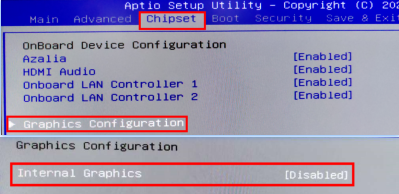
Disable the integrated graphics display adapter in the BIOS. Restart the IPC and press Del to enter the BIOS interface, click , press Enter, then click Internal Graphics and set it to Disabled, as shown below.
-
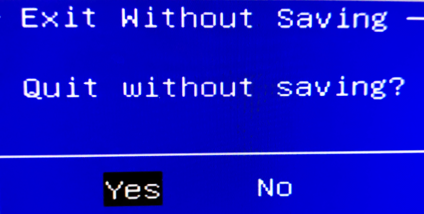
After completing the settings, press Esc to exit, and in the pop-up "Quit without saving?" dialog box, select Yes, as shown below.
Software Introduction
Software Features
After launching the Mech-GlueCheck software, the following interface is displayed:
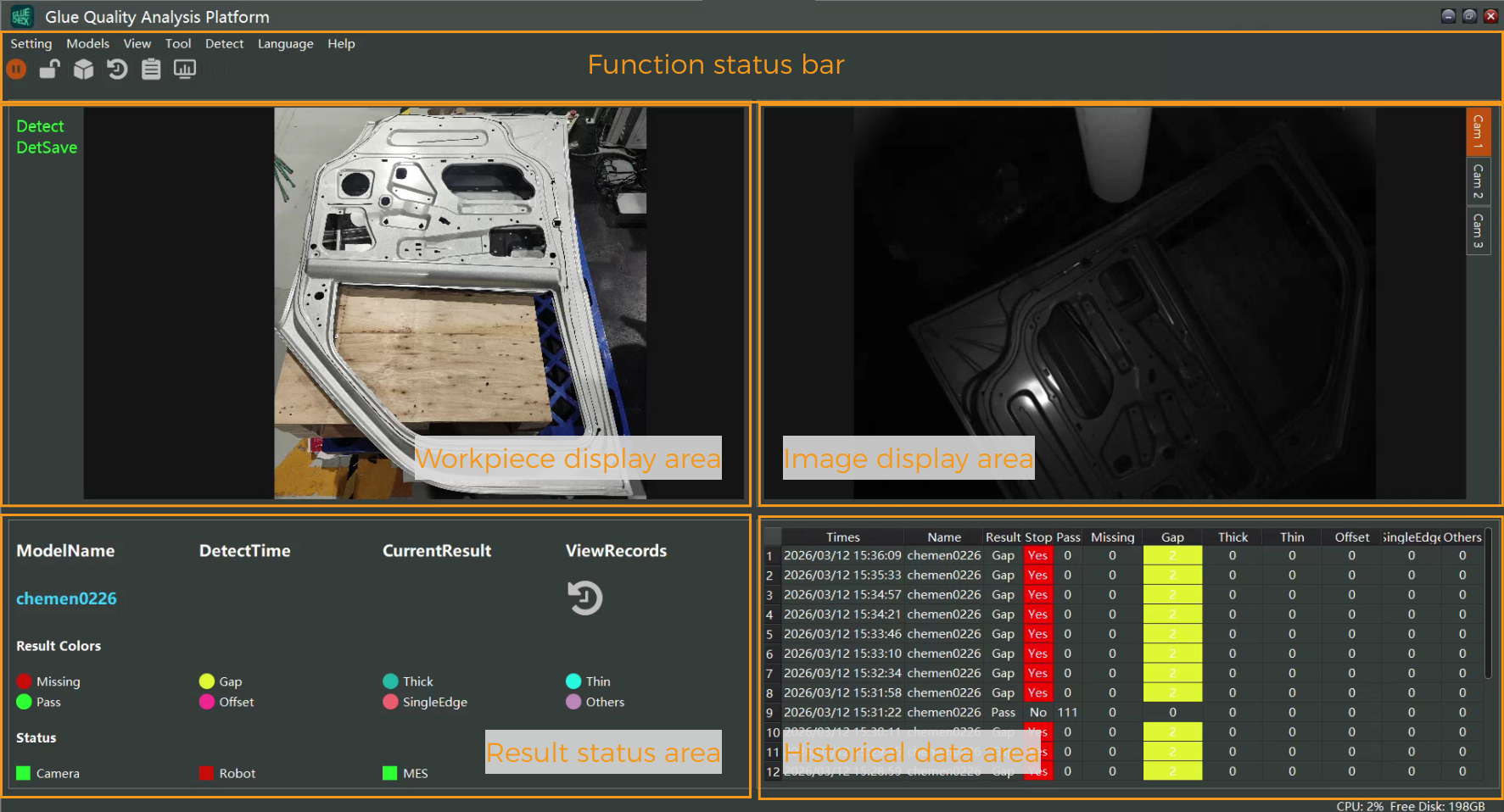
Function status bar |
Contains all functional modules of the software, including camera configuration, imaging settings, communication settings, model creation, historical data viewing, data backup, log management, and interface lock. |
|---|---|
Workpiece display area |
Used to display the workpiece image and glue path. |
Image display area |
Used to display the images acquired by the three cameras. |
Result status area |
Used to display the model in use, the inspection result, and the inspection time.
|
Historical data area |
Used to display historical inspection results. |
Camera Configuration
-
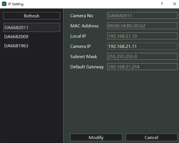
In the function status bar, click to open the Camera Settings interface.
-
Click Camera IP Settings, select the camera index on the left, and set the camera IP addresses for the three cameras respectively. The camera IPs must be on the same subnet as the local IP, and the last segment must not duplicate the last segment of the local IP.
-
After completing the settings, click Modify to save.
Imaging Settings
-
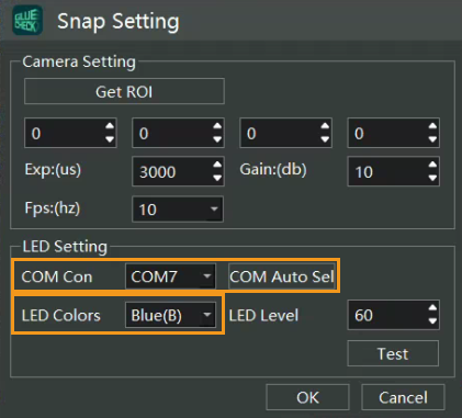
In the function status bar, click to open the Imaging Settings interface.
-
Set parameters such as Exposure, Gain, and Frame rate. To switch the LED color, select the correct COM port number, or click Auto-select COM for automatic connection.
-
After completing the settings, click OK to save.
Communication and Protocol Settings
-
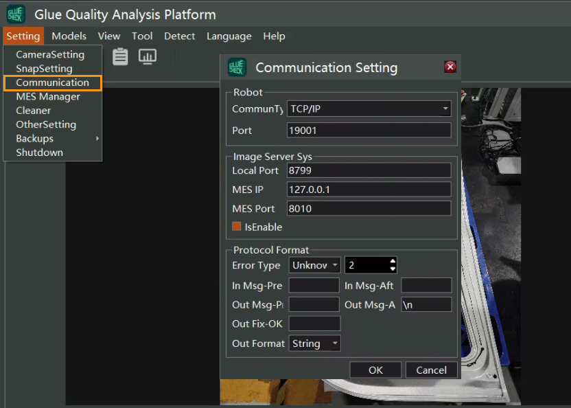
In the function status bar, click to open the Communication Settings interface.
-
Configure TCP/IP communication. As the server side, the software only needs the Communication port to be set.
-
Configure the communication protocol. You can set the Input prefix, Input suffix, Output prefix, and Output suffix, and customize the numeric codes corresponding to bead categories. Bead categories include Not detected, OK, Bead break, Too wide, Too narrow, Offset, Missing bead, Overflow, and Other.
-
After completing the settings, click Confirm to save.
The communication protocol between the robot and the software defines two types of commands: triggering image acquisition and obtaining inspection results. The overall inspection workflow is as follows.
-
The robot sends the command: S#StyleID#SegID.
-
The robot triggers the cameras via I/O signals to acquire images.
-
The robot starts the gluing operation.
-
The robot completes the gluing operation.
-
The robot sends the command: E.
-
The robot stops the I/O trigger signal.
-
The robot sends the command: DetRes to request the inspection result from the vision system.
-
The vision system returns the inspection result.
The detailed sequence is shown below. The robot must send the start command for each bead segment, S0101, before the hardware trigger turns on the light source and captures images, to better ensure acquisition consistency. Likewise, the end command for each bead segment, E, must be sent after completing the hardware-triggered acquisition.

No. |
Protocol operation |
Robot sends |
Robot receives |
||
|---|---|---|---|---|---|
Command |
Example |
Command |
Example |
||
1 |
VIN information |
The robot sends the command: Carinfo,xxxxxx Here, Carinfo is the protocol name, and xxxxxx is the VIN of the current model. This protocol is optional and is sent before starting inspection. |
Carinfo,C57019 |
Success: None Failure: None |
Success: None Failure: None |
2 |
Start of vision inspection |
The robot sends the command: S#ModelID#SegmentID |
S0701 |
Success: None Failure: None |
Success: None Failure: None |
3 |
Camera capture |
Hardware trigger, output high-level continuous signal. |
- |
- |
- |
4 |
End of vision inspection |
The robot sends the command: E |
E |
Success: None Failure: None |
Success: None Failure: None |
5 |
Camera stop capturing |
The robot stops the I/O trigger and stops the high-level continuous signal. |
- |
- |
- |
6 |
Retrieve inspection result |
The robot sends the command: DetRes |
DetRes |
Success: Returns the inspection result code. 1: OK 2: Missing bead 3: Bead break 4: Offset 5: Too wide 6: Overflow Failure: -1 |
Success: 1 Failure: -1 |
Model Creation
Acquire Images
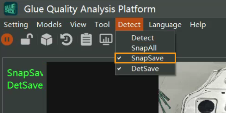
In the function status bar, click . The robot will then run at production speed and trigger acquisition, and the software will start capturing images. The save path is data/imageData/realImage under the software installation directory.
|
The order of turning on the light source and the trigger commands must strictly follow the requirements of Communication and Protocol Settings. |
Create a Model
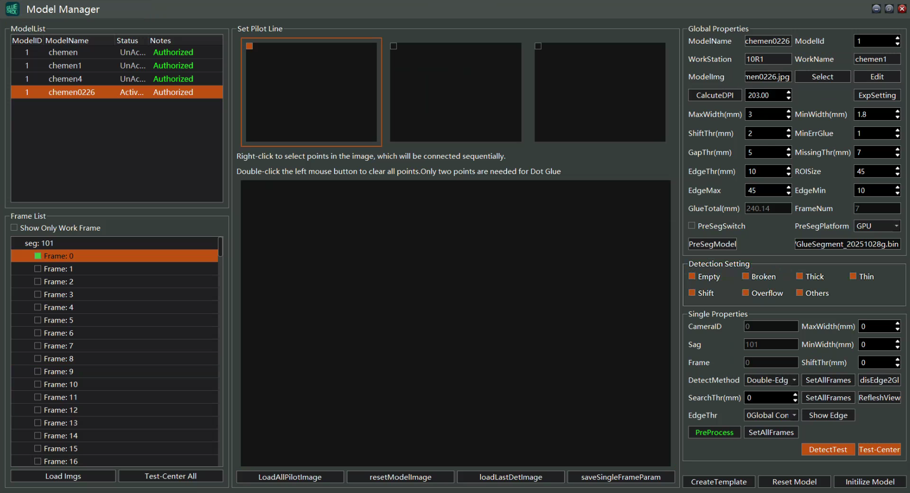
In the function status bar, click to open the Model Management interface.
Load Images
Click Load Images, then under the software installation directory select data/imageData/realImage/<current model number>/<latest date>/<latest image set> to load the currently acquired images.
Select an image frame to draw the path
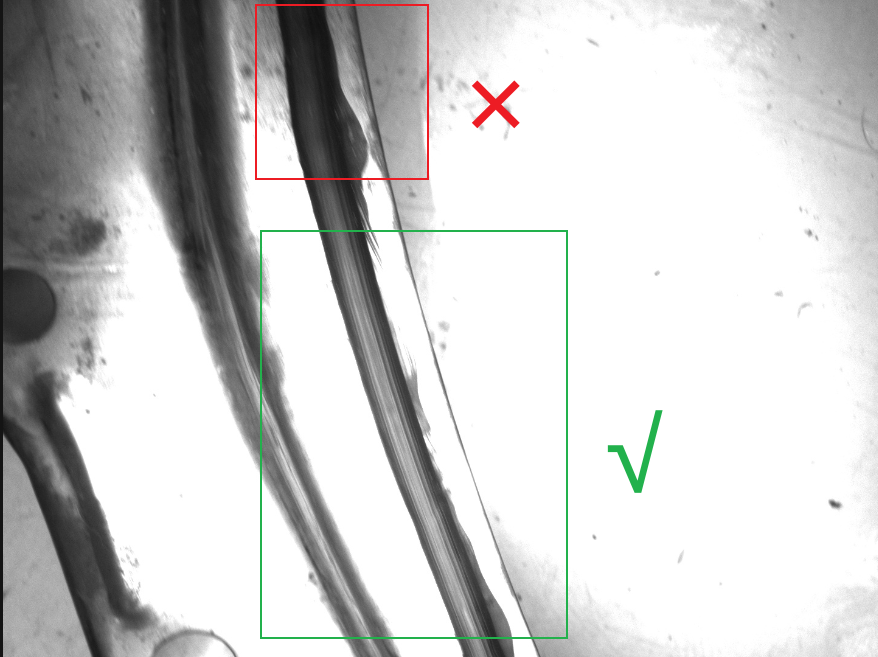
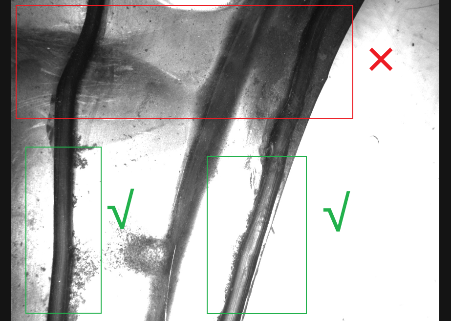
Choose an image frame where the bead segment has clear contrast with the background to draw the path. If the contrast is not clear in the current frame, it is not recommended to use that frame for path drawing, otherwise it may lead to false detections, abnormal results, or failures. You can move forward or backward to a frame with more pronounced contrast and then draw the path for that bead segment.
|
|
Set Basic Parameters
-
Set the model name and model ID. These are the unique identifiers in model management and must not be duplicated across models. The model ID must also be consistent with the ID used in the robot communication protocol.
-
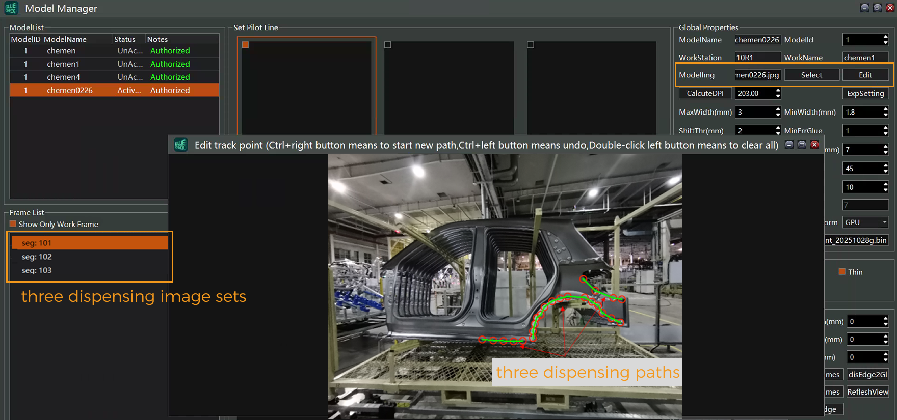
To display the gluing path in real time on the main interface, you need to select the workpiece image during model creation and draw the corresponding gluing path. The number of paths must match the number of groups of actual gluing images; otherwise model creation will fail.
-
After completing the above settings, click Create Model and wait for the model to be generated. If creation fails, correct the errors according to the prompts and try again.
Other Model Parameters
The table below describes the parameters involved in model creation.
-
Global model parameters
Parameter Name Type and Range Description Model name
String
Must not be duplicated across models; otherwise, an existing model may be overwritten.
Model ID
Number, [0,99]
Must not be duplicated across models and must be consistent with the ID in the robot protocol.
Station number
String
-
Part name
String
The part name displayed in statistics tables and reports. Different models can use the same part name. If left empty, it will default to the model name.
Compute DPI
Float, [50,1000]
Used to compute glue width and length; it can be auto-calculated using a calibration target. If the computed glue width is inaccurate, recalibrate this parameter.
Maximum glue width
Integer, [1,81]
Maximum alarm glue width, in mm. When the measured glue width exceeds this value, the system will alarm as Too wide or Bead break.
Minimum glue width
Float, [0.5,80]
Minimum alarm glue width, in mm. When the measured glue width is below this value, the system will alarm as Too narrow or Bead break.
Maximum offset
Integer, [1,100]
In mm. When the deviation between the glue and the model exceeds this threshold, the system will alarm as Offset or Missing bead.
Bead break threshold
Integer, [1,100]
Sets the bead break threshold, in mm. When the break length exceeds this threshold but does not reach the missing-bead threshold, the system will alarm as Bead break; otherwise it is ignored and judged OK.
Missing-bead threshold
Integer, [1,100]
Sets the missing-bead threshold, in mm. When the break width exceeds this threshold, the system will alarm as Missing bead.
Overflow threshold
Integer, [1,100]
In mm. When the length of the glue near the edge exceeds this threshold, the system will alarm as Overflow.
Path display box size
Integer, [4,100]
Used to set the size of the path display box.
Edge threshold Max
Integer, [1,200]
Sets the maximum threshold for image edge detection.
Edge threshold Min
Integer, [1,150]
Sets the minimum threshold for image edge detection.
Pre-segmentation model master switch
BOOL
Controls whether to use a pre-segmentation model for feature segmentation. When enabled, the system automatically loads the pre-segmentation model.
Pre-segmentation platform
GPU or CPU
Selects the platform on which the pre-segmentation model runs. The CPU platform is suitable for testing, has lower efficiency, and cannot meet real-time detection; the GPU platform is more efficient and requires an NVIDIA GeForce RTX 3050 or higher GPU.
Load pre-segmentation model
-
Used to load the pre-segmentation model file.
-
Detection switches
Specifies the alarm behavior for each error type.
-
Per-frame detection parameters
Parameter name Type and range Description Maximum glue width
Integer, [0,81]
If this value is less than 0.1, the global maximum glue width is used; otherwise, the current value is used as this frame’s maximum glue width.
Minimum glue width
Float, [0.0,80.0]
If this value is less than 0.1, the global minimum glue width is used; otherwise, the current value is used as this frame’s minimum glue width.
Maximum offset
Integer, [0,80]
If this value is less than 0.1, the global maximum offset is used; otherwise, the current value is used as this frame’s maximum offset.
Edge threshold
Default: Global contrast
-
Maximum search width
Float, [0,50]
When set to 0, the search width is calculated automatically. If the value is smaller than the minimum glue width, it is automatically set to the minimum glue width.
Model Parameters—Compute DPI
To accurately calculate parameters such as glue width and length, camera calibration is required. Mech-GlueCheck provides a method to automatically compute the DPI value; please prepare the calibration target shown below in advance.
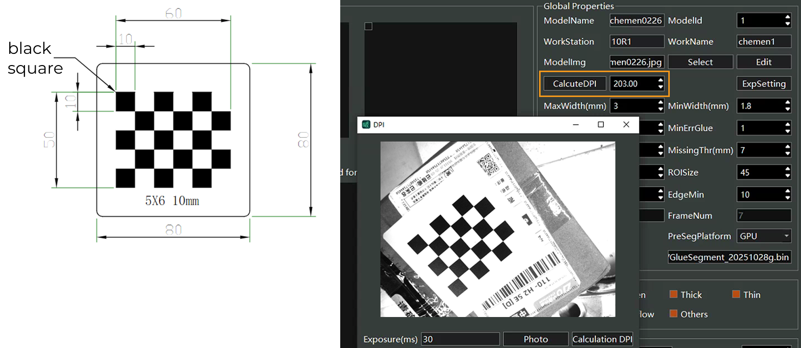
Place the calibration target at the normal working distance under the camera, keeping the distance the same as in normal gluing; otherwise the computed DPI may be inaccurate. Click Capture to obtain a properly exposed image, and then the DPI value can be computed.
Model Parameters—Search Range Settings
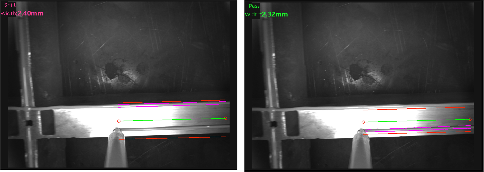
During model creation, the red regions on both sides of the guide line (green line) represent the search range for glue inspection. Areas outside the search region are not searched. In actual operation, the glue path often deviates from the guide line to some extent. If the bead deviates beyond the search region, it will be falsely reported as Missing bead, causing detection failure. Within the search region, if the bead deviation exceeds the Maximum offset setting, the system will trigger an Offset alarm. Therefore, the search region is a key parameter affecting detection accuracy. The following five parameters affect the search range for glue inspection.
| Parameter Type | Parameter Name | Parameter Priority Order |
|---|---|---|
Global parameter |
Maximum glue width (mm) |
3 |
Global parameter |
Maximum offset (mm) |
3 |
Per-frame detection parameter |
Maximum glue width (mm) |
2 |
Per-frame detection parameter |
Maximum offset (mm) |
2 |
Per-frame detection parameter |
Maximum search width (mm) |
1 |
By default, when the maximum search width is 0, the parameter is ignored and the actual search width is computed as: Search width = Maximum offset × 2 + Maximum glue width. When the maximum search width is greater than 0, the system uses that value as the final search width (the final value will not be less than the maximum glue width).
Selection of maximum glue width and maximum offset: if the per-frame maximum glue width is greater than 0, use the per-frame value; otherwise use the global maximum glue width. The selection of maximum offset follows the same rule.
As shown below, different search widths may lead to different results. Set the search width according to the dispensing process: if the process is stable with small deviations, use a smaller search range for faster and more accurate detection; if deviations are larger, increase the search range or the maximum offset to ensure the bead always remains within the search region.
Model Parameters—Edge Threshold Settings
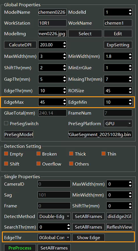
Mech-GlueCheck relies on clear glue edges when analyzing images. By default, the system uses the global edge threshold. When the edges are clear with strong contrast, you can raise the edge threshold appropriately to enhance stability. Each frame can also have an individual edge threshold to handle different scenarios. Note that when pre-segmentation is enabled, the edge threshold parameter becomes ineffective.
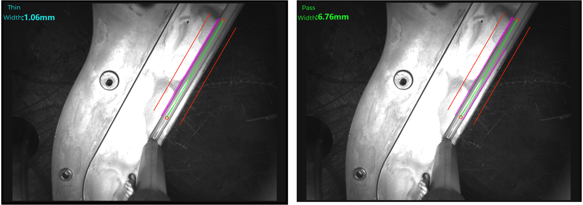
When the per-frame edge threshold is set to 1 (high contrast, high speed (45,15)) versus 5 (low contrast, low speed (10,5)), the difference in detection results is as shown below. When the glue contrast is low, you can lower the threshold parameter appropriately to improve detection rate.
Model Parameters—Image Enhancement Settings
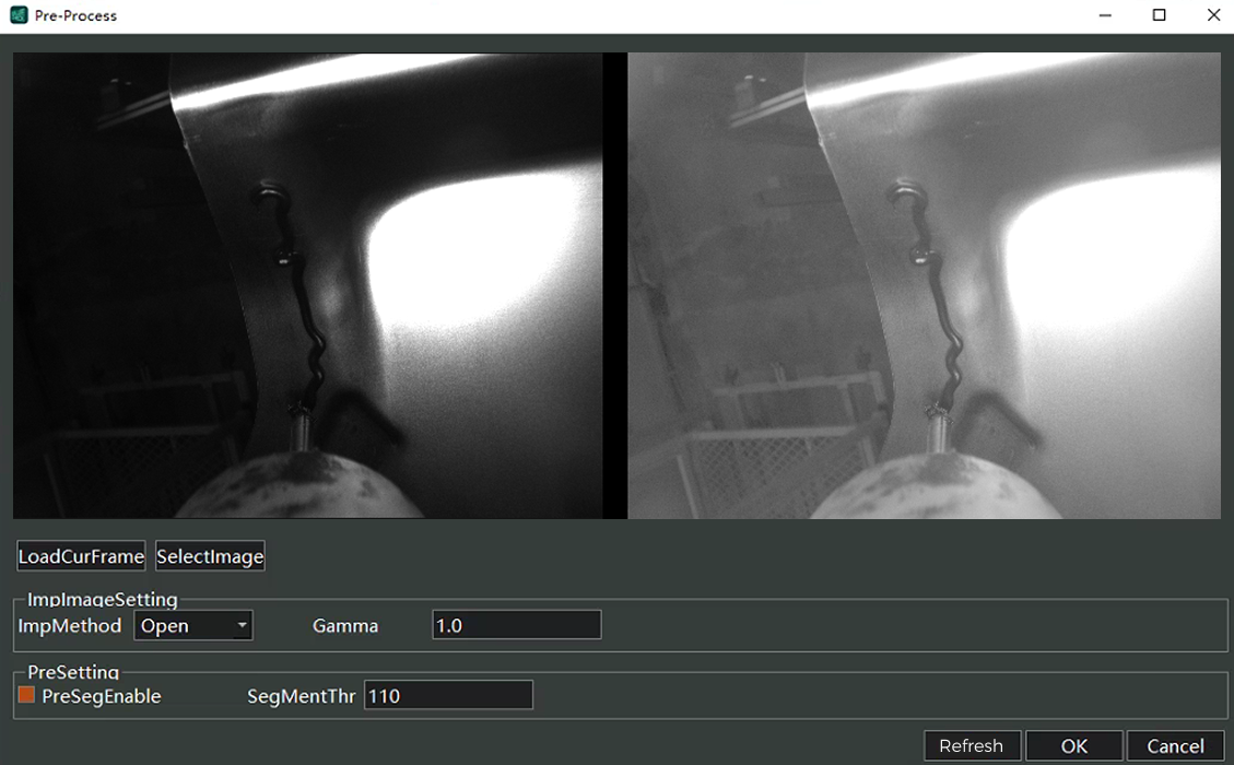
In preprocessing, the system provides a Gamma-based image enhancement function, which can be enabled for low-contrast frames to improve detection. By default, image enhancement is disabled.
Model Parameters—Pre-Segmentation Settings
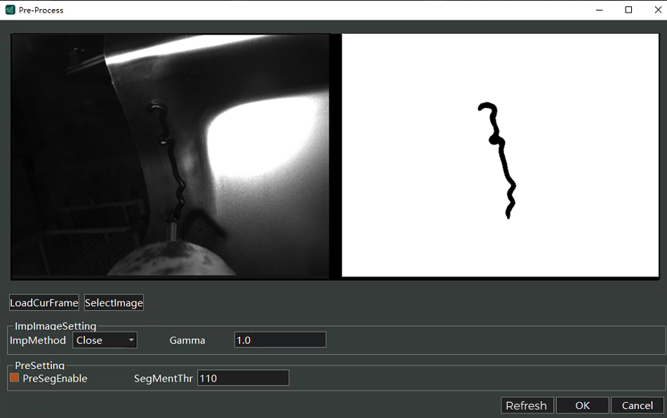
In preprocessing, the system provides an image segmentation function. For images with complex backgrounds, this can significantly improve detection. The system uses a deep-learning-based segmentation model, which requires labeled training samples. To achieve real-time detection, GPU hardware is required, specifically an NVIDIA GeForce RTX 3050 or higher.
All preprocessing functions, including pre-segmentation, can be set independently for each frame. Pre-segmentation requires that the global pre-segmentation switch be enabled.

Historical Data Query
-
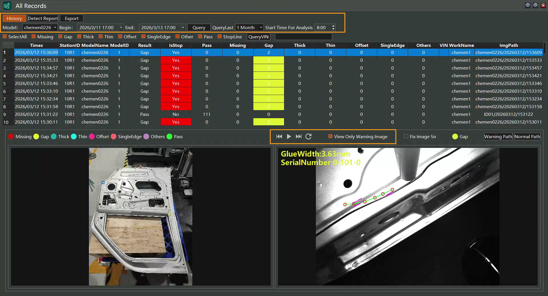
In the function status bar, click . In the pop-up Inspection History Data interface, click History Query, select Model, set the start and end times, and click Query to view production images and warning images. To view only warning images, click Warning images only. Click the arrow button to view the next image.
-
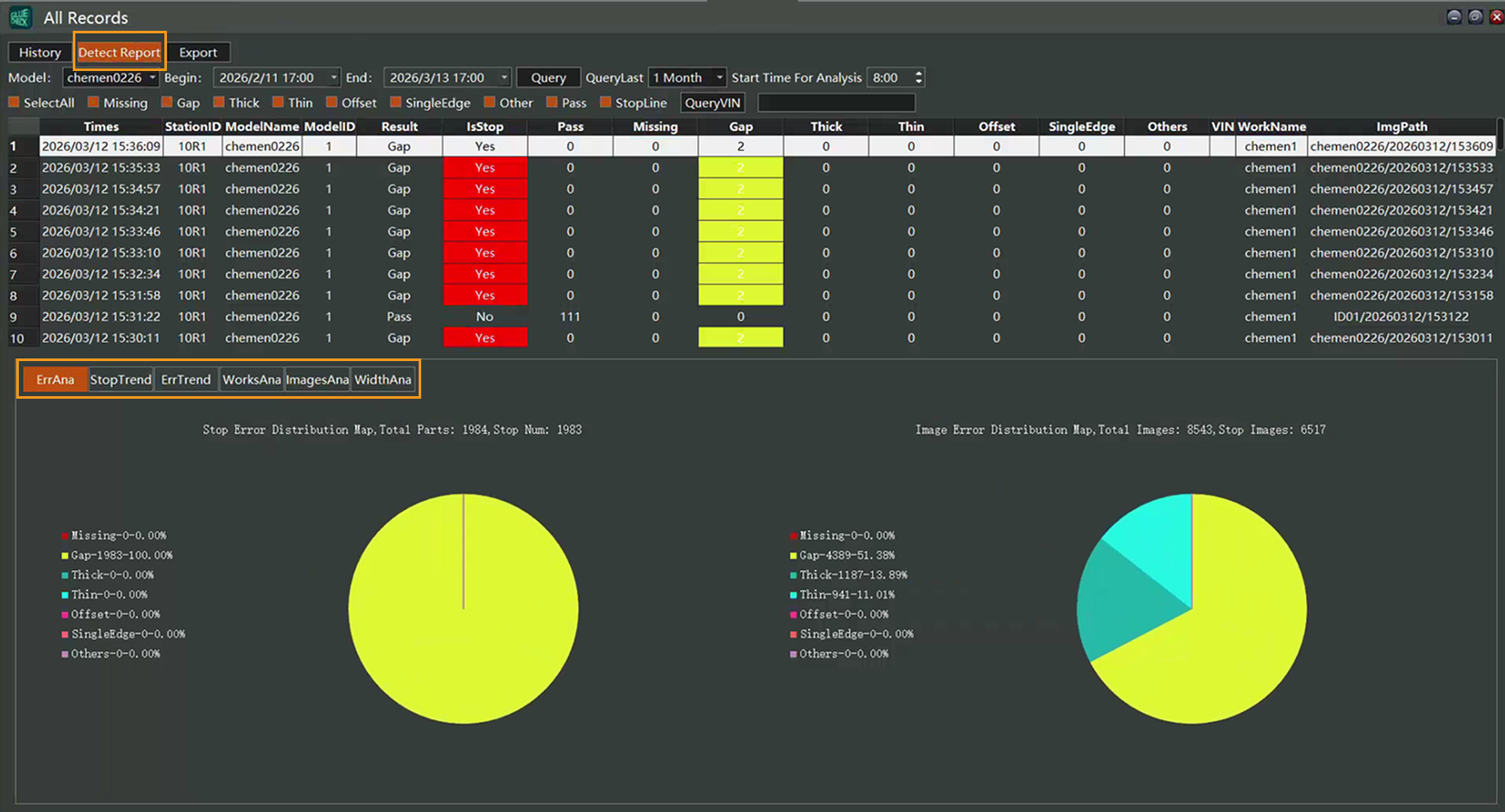
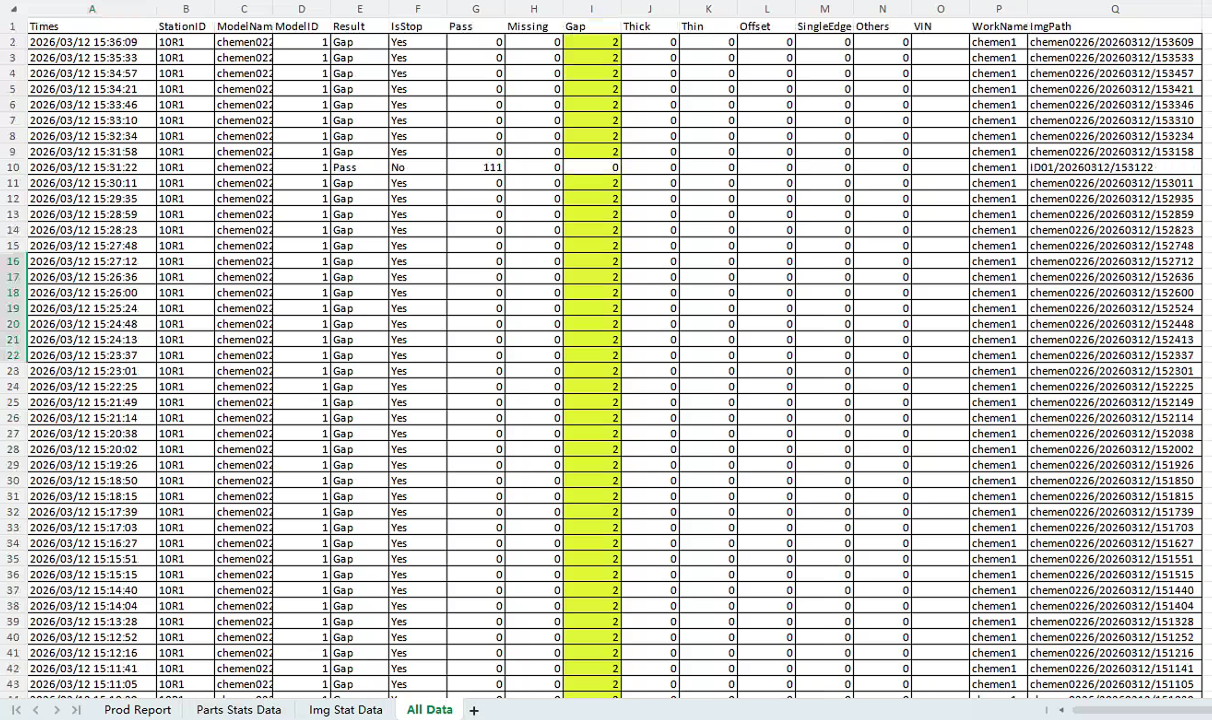
In the Inspection History Data interface, click Inspection Reports to view the error distribution chart, line-stop trend chart, error trend chart, part statistics table, image statistics table, and glue width chart.
-
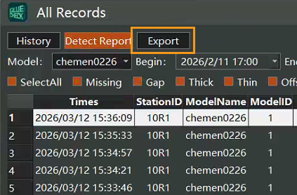
In the Inspection History Data interface, click Export to export production data (.xlsx file).
Robot Communication Settings
Connect to the Robot
Different robot brands vary in operation; this section uses a FANUC robot as an example. The interface and operating steps shown may vary slightly depending on the robot version. Please refer to the actual device.
When using a FANUC robot, the robot is controlled via the teach pendant. Before starting, you must complete the robot’s communication settings. After setting the IP address, import the pre-prepared PC programs into the teach pendant via a USB drive. The programs typically to be imported include: OPENPHOTO (open camera), CLOSEPHOTO (close camera), SWITCHMODEL (model switch), RECGHT (background run). The specific steps are as follows.
Verify Communication Option Packages
-
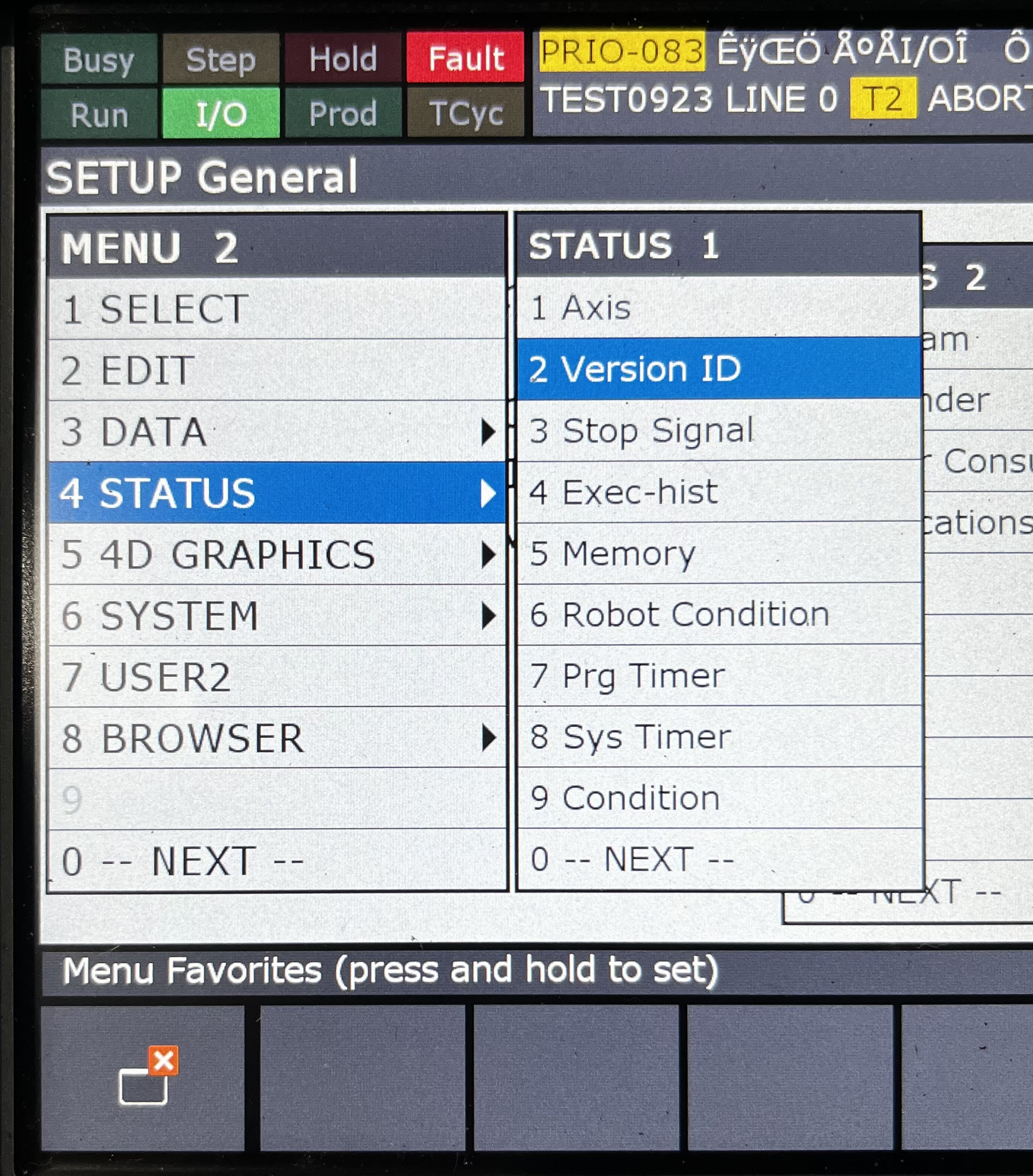
Press the MENU key to open the menu, and click .
-
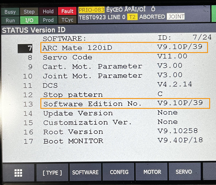
Determine the robot model and software version.
-
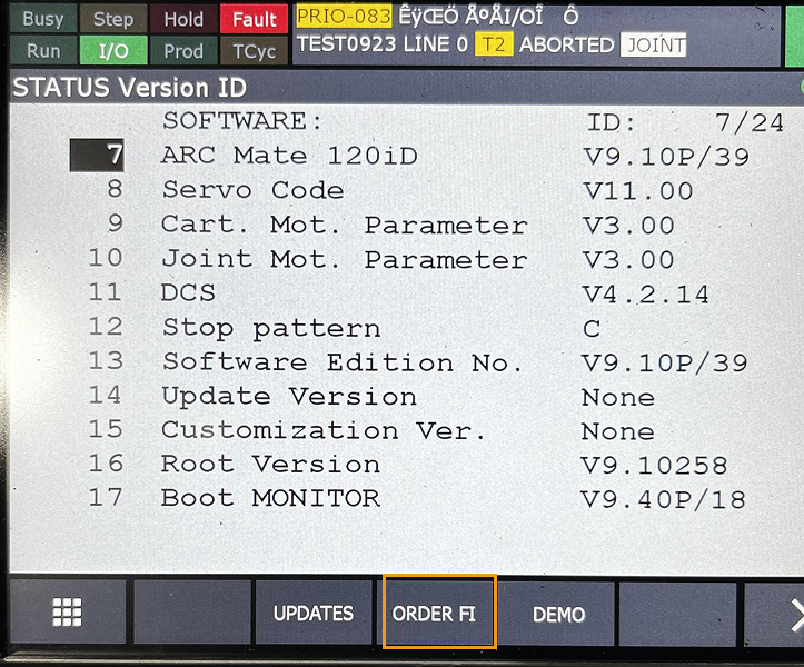
Click Order FI.
-
Confirm that the robot has the PC Interface communication option and the KAREL background option enabled.
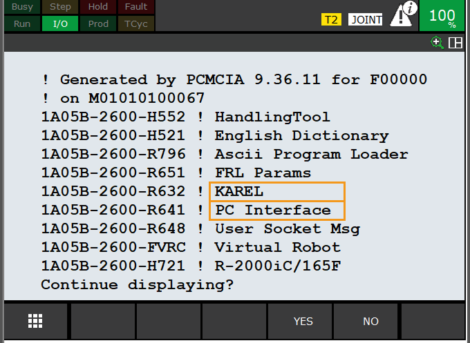
Import Programs
-
Open the teach pendant, click . On the FILE page, click UTIL, then select Set Device, as shown below.
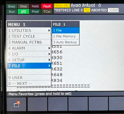
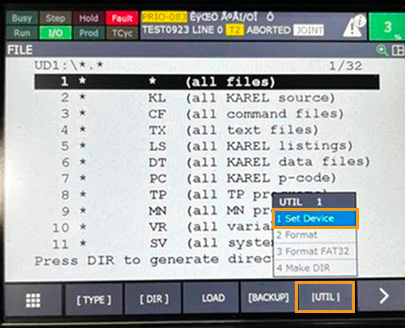
-
Select USB on TP (UT1:), click DIR, and select *.PC, as shown below.
When the USB drive is inserted into the teach pendant, select USB on TP (UT1:); when inserted into the controller cabinet, select USB (UD1:).
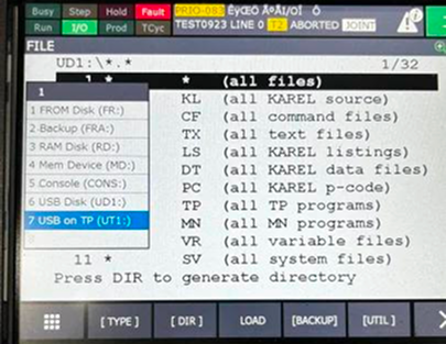
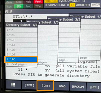
-
Click LOAD. In the confirmation dialog that appears, choose Yes; the program will then be imported into the teach pendant.
Please use a USB 3.0 drive, and the file system must be FAT32; otherwise, the program cannot be imported into the teach pendant.
Modify Communication Configuration IP
-
Press MENU to open the menu, and click .
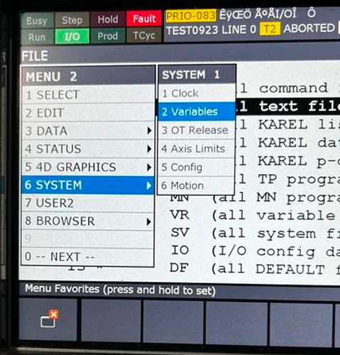
-
Change the system variable $KAREL_ENB to 1.
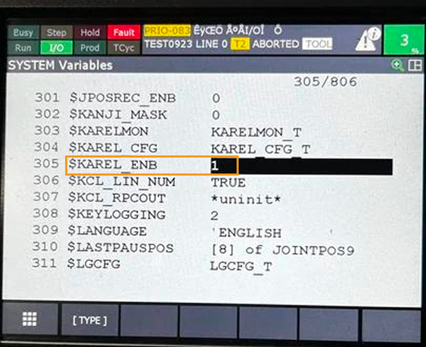
-
Press MENU to open the menu, and click .
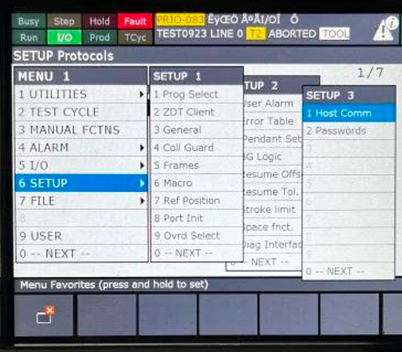
-
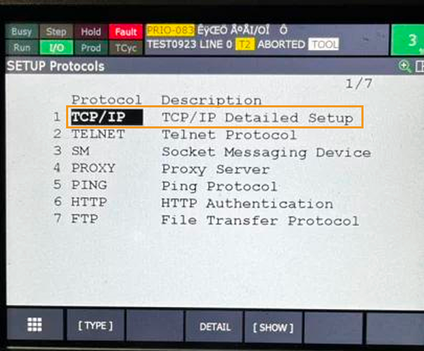
Select TCP/IP and press ENTER or F3.
-
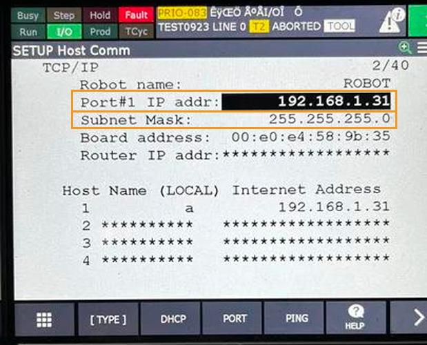
In the Port #1 IP addr line, enter the robot IP address, for example: 192.168.1.31.
-
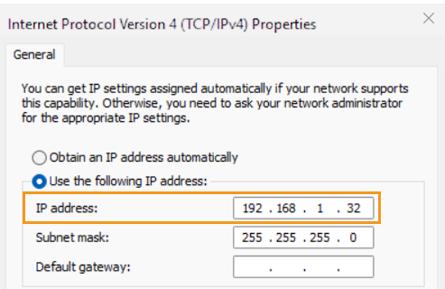
The host PC’s IP address must be on the same subnet as the robot’s IP address; for example, set the host PC’s IP address to 192.168.1.32.
-
After finishing the settings, reboot the robot to apply them.
-
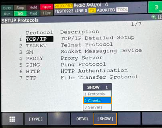
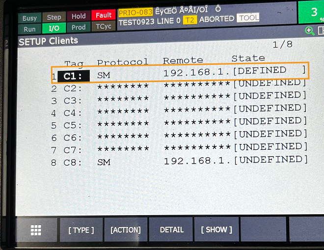
After the reboot, return to this page and click ; the robot acts as a client and the host PC as a server.
-
Select a label number; C1 is used here as an example. Press ENTER to enter.
-
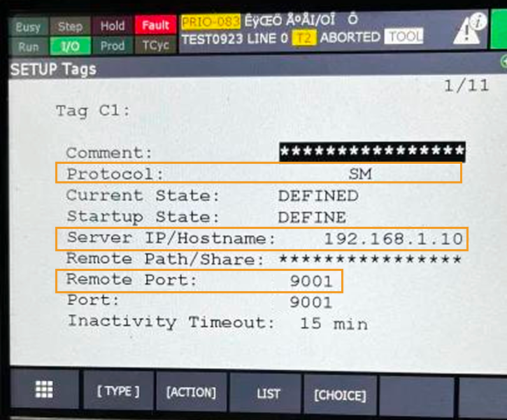
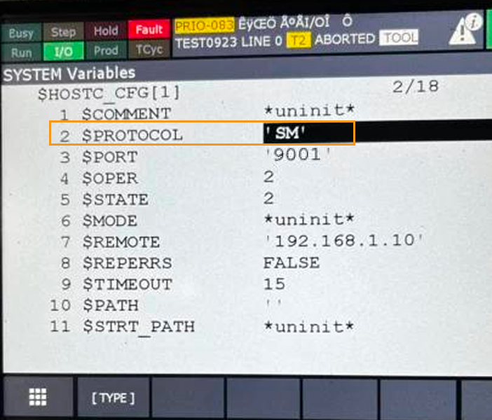
At Protocol, press F4 (CHOICE) and select SM.
-
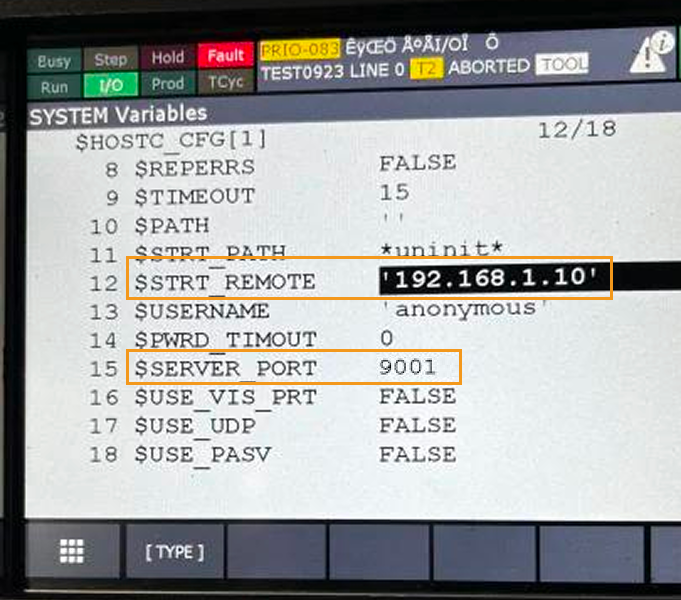
Set Current status to Undefined, enter the host PC’s IP address in Server IP/Host Name, and press ENTER.
-
Enter 9001 at Remote Port.
-
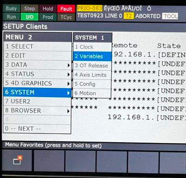
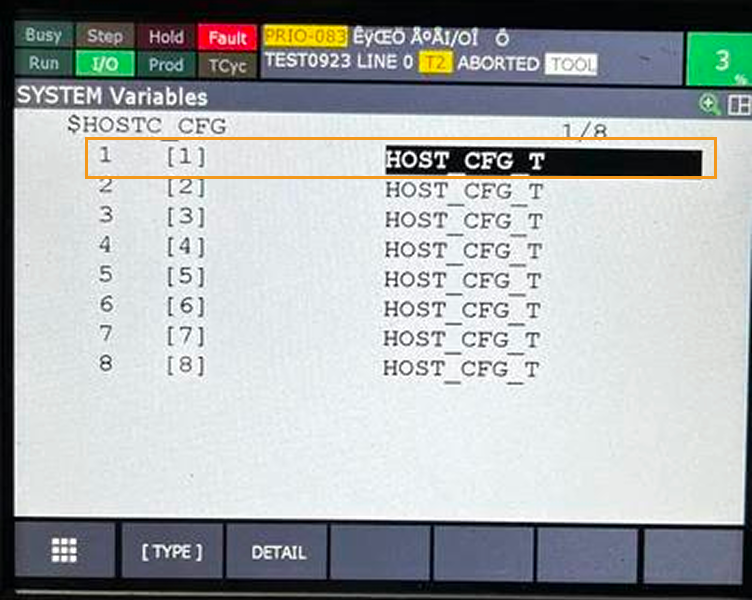
Press MENU to open the menu, and click .
-
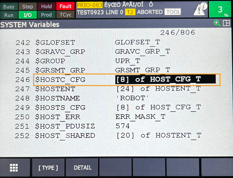
Select $HOSTC_CFG and press ENTER.
-
Because label C1 was selected, choose the first line, press ENTER, and check whether the parameters match the C1 settings.
Run a Program
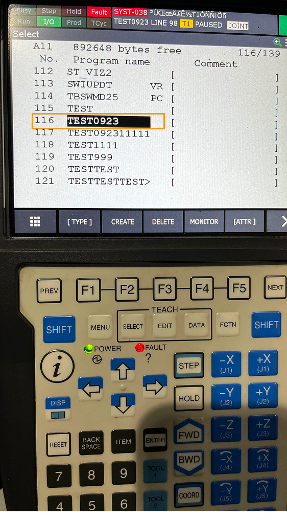
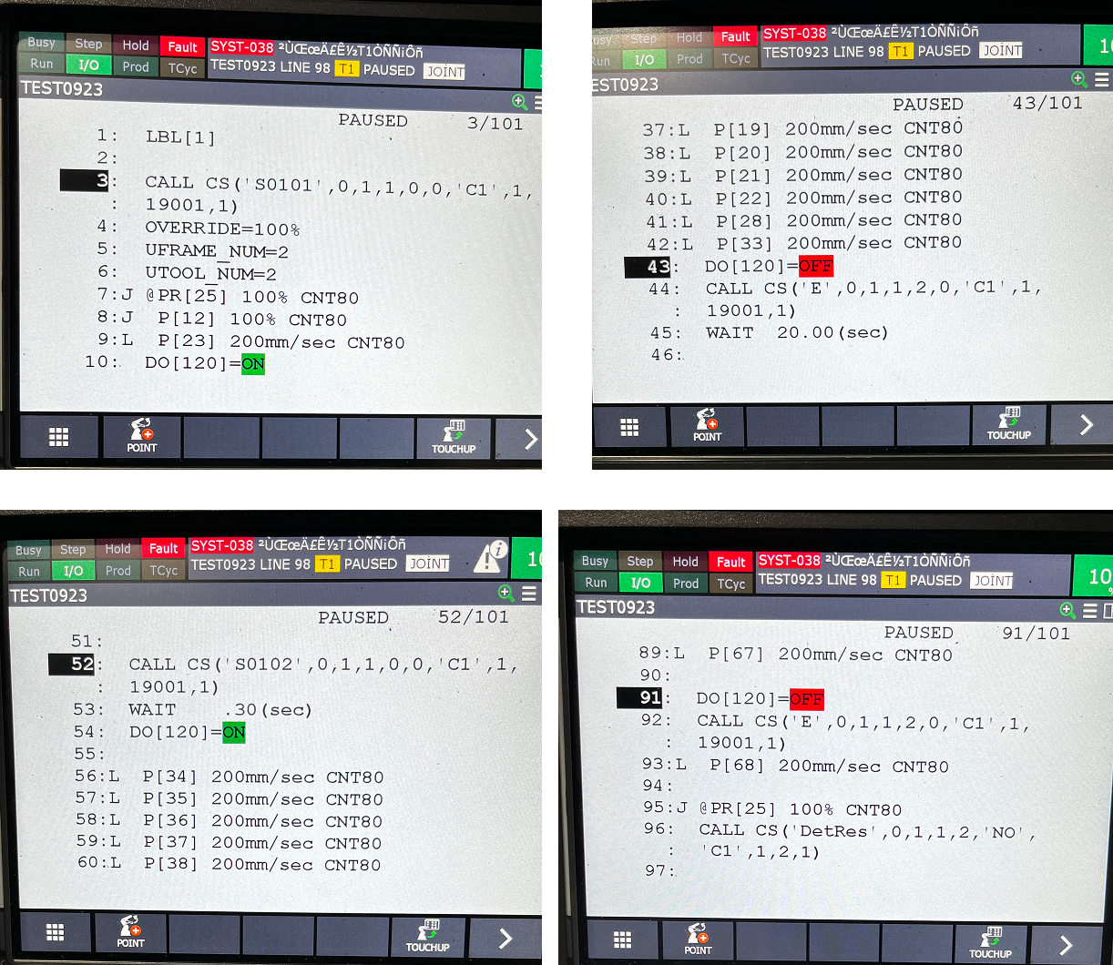
After the program has been imported, select the program you want to run. Using the calibration program TEST0923 as an example, hold the enable switch and select TEST0923, then press ENTER to enter the program. If there is an error alarm, press RESET to clear the alarm. Next, hold SHIFT and press STEP to switch from single-step to continuous mode, and finally press FWD to run the program, as shown below.
Network Connection
Connect one end of the cable to the camera; connect the power lead on the other end to the power supply, and connect the network cable to the industrial PC’s Ethernet port. Then check whether the Ethernet cable is connected correctly.
Check the Ethernet Cable Connection
When the Ethernet cable is connected to the industrial PC, observe whether the NIC indicator lights up or blinks. If the indicator does not light, the possible reasons are:
-
The camera power is not properly connected. Check the power lead at the camera end and the power adapter’s supply.
-
The network cable is not properly connected. Check whether the cable is fully seated both at the camera end and at the PC’s Ethernet port.
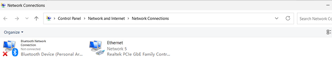
After confirming that the cable is properly connected, on the industrial PC open and locate the camera’s network adapter, as shown below.
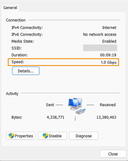
Double-click the connected network adapter and check the camera’s link speed. When the link speed shows 1.0 Gbps, the camera’s network connection is good and it can be used normally; if the link speed is below 1.0 Gbps, recheck the camera cable and connector, otherwise normal camera operation may be affected.
Modify Network Adapter Properties
Select one of the camera’s network adapters, right-click Properties, click Configure, and under the Advanced tab set the following:
-
Set Transmit Buffers to the maximum value 2048 to enhance transmission performance.
-
Set Receive Buffers to the maximum value 2048 to enhance reception performance.
-
Set Jumbo Frame to 9014 Bytes to reduce CPU usage and improve line efficiency.
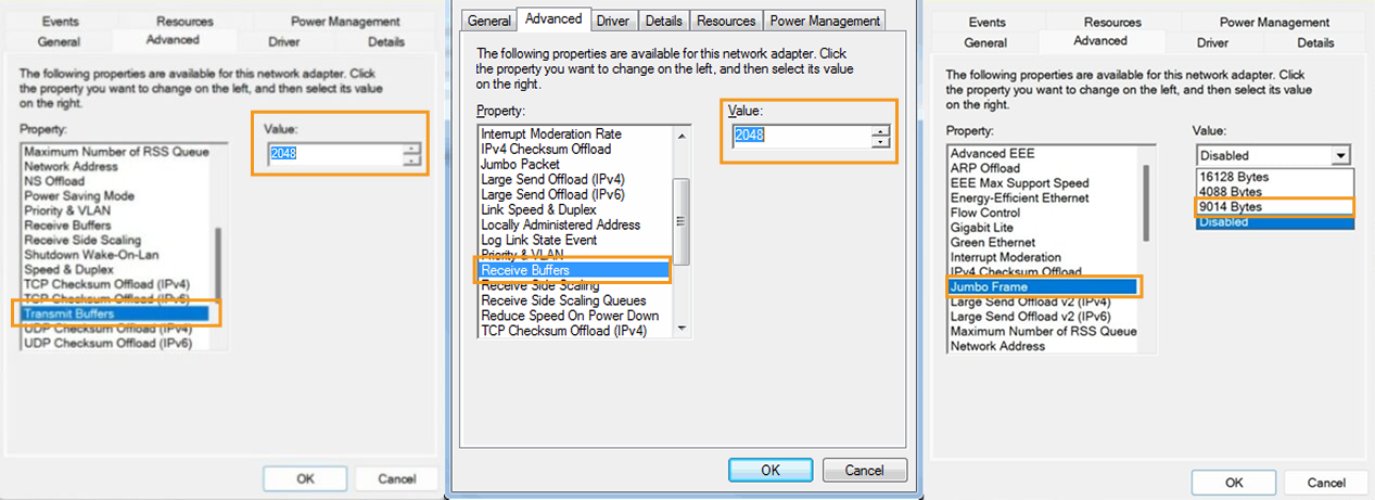
After finishing, switch to the Power Management tab, uncheck Allow the computer to turn off this device to save power, and then click OK to complete the adapter property settings.
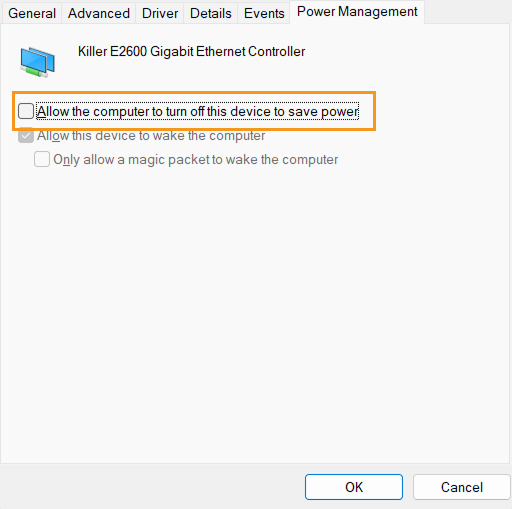
Configure all network adapters following the steps above.
Modify the Network Adapter IP
-
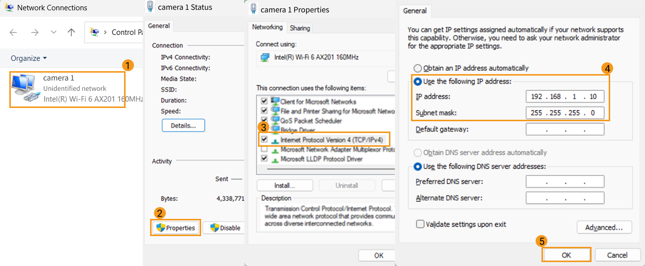
Double-click the network adapter corresponding to the camera whose IP you need to modify, and click Properties.
-
Double-click Internet Protocol Version 4 (TCP/IPv4).
-
In the properties panel, select Use the following IP address, and set the camera IP address to 192.168.xxx.xxx. The three monocular cameras must be placed on different subnets, and avoid conflicts with the subnet used by the robot. Do not set any octet of the IP address to 0.
-
Set the Subnet mask to 255.255.255.0. The default gateway does not need to be configured.
-
After completing the settings, click OK to save the configuration, as shown below.
Maintenance
Package Contents
To facilitate future storage and transportation, please properly keep the packaging box and packing materials after unpacking. The standard packing list is shown in the table below:
| Name | Specification |
|---|---|
Mech-Eye Glue Detection Camera |
1 unit |
Camera power I/O cable |
15 m, 1 cable |
Camera Ethernet cable |
15 m, 3 cables |
Robot Ethernet cable |
15 m, 1 cable |
Power adapter |
1 unit |
Camera adapter |
1 unit |
Industrial PC |
1 unit |
Cabinet |
1 unit |
Regular Inspections
| Inspection Item | Maintenance Action | Tools |
|---|---|---|
Trinocular camera window |
Check whether the screws are loose |
Phillips screwdriver |
Trinocular camera cover |
Check whether the screws are loose |
Allen key M1.5 |
Trinocular camera mount |
Check whether the mount is loose |
Allen key M5 and Allen key M6 |
Trinocular camera window |
Check whether the outer glass has dust on it |
Dust cloth |
Industrial PC |
Check whether the chassis has dust and whether the dust filters are clean |
Air compressor or air gun |
C drive |
Check C drive usage |
- |
Troubleshooting
| Description | Resolution |
|---|---|
Network speed does not reach 1 Gbps |
|
RS-485 serial port communication failure |
|
The video stream cannot be opened despite normal network connectivity. |
Upgrade the camera firmware again. |
The optical engine did not initiate the light source. |
|
Optical engine electrical leakage |
|
|
If the issue persists, please contact Mech-Mind technical support. |
Storage
The warehouse for long-term storage of Mech-Eye Glue Detection Camera should meet the following conditions:
-
Ambient temperature: -10 to 60°C
-
Relative humidity: ≤ 80%
Transportation
Mech-Eye Glue Detection Camera complies with the relevant requirements of transportation standards for road, rail, air, and water transport.
During transportation, pay attention to the following: the camera must be kept away from severe shocks, rain, chemical corrosives, and harmful gases.
Disclaimer
It is strongly recommended to use the power supply and cables provided by Mech-Mind to ensure compliance with the safety and EMC standards. Mech-Mind shall not be liable for any issues caused by using the power supply and cables provided by a third party.
Trademark and Legal Statement
Mech-Mind and Mech-Mind series logos including  are registered trademarks of Mech-Mind Robotics Technologies Co., Ltd. and other related entities.
© Copyright 2026, Mech-Mind Robotics Technologies Co., Ltd.
Unless authorized in writing in advance by Mech-Mind Robotics Technologies Co., Ltd. (“Mech-Mind”), no part of the trademarks shall be used, reproduced, modified, transmitted, transcribed, or used or sold with other products as a bundle by any entity or individual in any form for any reason.
Any infringement of Mech-Mind’s trademark rights will be punished in accordance with the law.
Mech-Mind reserves all rights regarding this user manual. According to copyright laws, unless authorized by Mech-Mind, this user manual shall not be reproduced, modified, or issued in part or in its entirety by any entity or individual. Users who purchased and use the product may download, print, or copy the user manual for personal use or use inside the belonging organization. Unless authorized by Mech-Mind, the contents of the user manual may not be used for any other purposes.