Preparation Before Calibration
Before performing translation calibration or rotation calibration, complete the basic configuration, camera configuration, communication configuration, and calibration configuration according to the actual calibration method.
Basic Configuration
Complete the corresponding basic configuration according to the calibration type you need to perform.
-
Translation Calibration
-
Rotation Calibration
-
Install the gantry robot, and ensure that the site environment is stable and free of obvious vibration.
-
Install the camera mounting frame and the camera. Do not move the camera or adjust its mounting position before or after calibration.
-
Prepare the project used for calibration, and ensure that the project can output valid feature points.
-
Determine whether robot motion affects the camera position according to the actual situation.
-
Complete translation calibration and save a valid translation calibration file.
-
Ensure that the gantry robot can rotate at a constant speed.
-
Prepare the project used for calibration, and ensure that the project can stably output valid feature points at each rotation position.
Camera Configuration
-
Open the project used for calibration, and select the camera used for calibration in the 2D Camera Step. If no camera is available in the list, click the Camera management button, add and connect a camera in the 2D Camera Management tool, and then return to select the camera in the 2D Camera Step.
-
Acquire one image or acquire images continuously, and adjust camera parameters to ensure that the image brightness is appropriate and that the calibration features are clearly visible.
-
After completing camera configuration, keep the camera parameters and mounting position unchanged.
Communication Configuration
When performing automatic calibration or Calibration Update, you need to configure a custom communication service. If you use only manual calibration, you can skip this section.
-
Open Communication Configuration and go to the Service configuration page.
-
Create a TCP or PLC service according to the communication method of the external device, and complete the related custom communication service configuration.
-
Enable the communication service, and confirm that the external device can communicate with the software properly.
|
Calibration Configuration
Before using automatic calibration or Calibration Update, you need to configure calibration communication. Select to open the Calibration Configuration window, and then go to the Calibration communication tab.
Calibration Communication
In the Calibration communication tab, complete the following configuration according to the communication method used by the external device.
-
TCP Communication
-
PLC Communication
-
In the Basic settings area, select the TCP custom communication service, and then set Command ID and Delimiter.
-
In the Request format area, set the positions of the fields that the external device sends to the software.
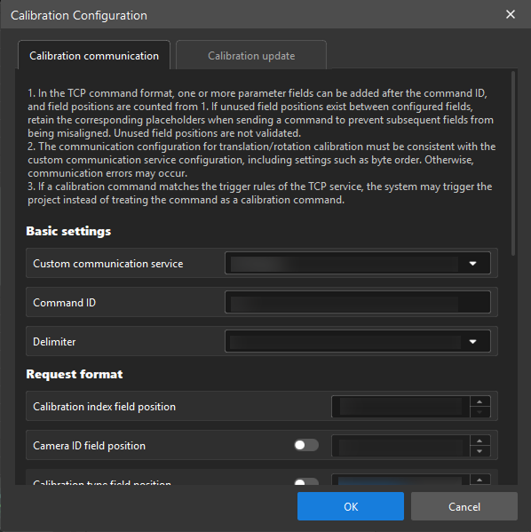
Field Description Calibration index field position
The position of the calibration index in the command. The calibration index is used to distinguish different calibration tasks.
Camera ID field position
The position of the camera ID in the command. If camera ID verification is not required, you can disable this field.
Calibration type field position
The position of the calibration type in the command. After enabling this field, you also need to set Translation field value and Rotation field value. If calibration type verification is not required, you can disable this field.
Action type field position
The position of the action type in the command. You also need to set the field values for Start, Continue, and End.
Coordinate field position
The positions of X, Y, and RZ in the machine pose within the command.
-
In the Response format area, set the positions of the fields that the software returns to the external device.
Field Description Calibration index field position
The position of the calibration index in the returned data.
Camera ID field position
The position of the camera ID in the returned data. If you do not need to return the camera ID, you can disable this field.
Calibration type field position
The position of the calibration type in the returned data. If you do not need to return the calibration type, you can disable this field.
Status field position
The position of the calibration status in the returned data. You also need to set the field values for Running, Done, and Fail.
| In the TCP command format, one or more parameter fields can be added after the command ID, and field positions are counted from 1. If unused field positions exist between configured fields, retain the corresponding placeholders when sending a command to prevent subsequent fields from being misaligned. Unused field positions are not validated. |
-
In the Basic settings area, select the PLC custom communication service, then select Trigger variable name and set Trigger value.
| Calibration communication over PLC supports numeric variables only. The software processes byte order according to the selected PLC custom communication service: Siemens S7 Client uses the ABCD byte order, Mitsubishi MC Client uses the CDAB byte order, and Modbus TCP Master uses the same byte order as configured in the selected custom communication service. |
-
In the Request format area, select the variables that the external device uses to write calibration data to the software, and then set the variable values corresponding to each action.
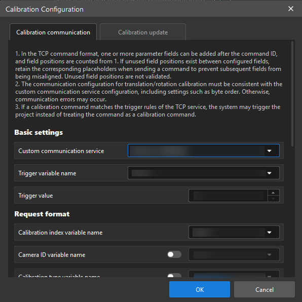
Field Description Calibration index variable name
The variable used to write the calibration index.
Camera ID variable name
The variable used to write the camera ID. If camera ID verification is not required, you can disable this field.
Calibration type variable name
The variable used to write the calibration type. After enabling this field, you also need to set Translation variable value and Rotation variable value. If calibration type verification is not required, you can disable this field.
Action type variable name
The variable used to write the action type. You also need to set the variable values for Start, Continue, and End.
Coordinate variable name
The variables used to write X, Y, and RZ in the machine pose.
-
In the Response format area, select the variables that the software uses to write back calibration results, and then set the variable values corresponding to each status.
Field Description Calibration index variable name
The variable used to return the calibration index.
Camera ID variable name
The variable used to return the camera ID. If you do not need to return the camera ID, you can disable this field.
Calibration type variable name
The variable used to return the calibration type. If you do not need to return the calibration type, you can disable this field.
Status variable name
The variable used to return the calibration status. You also need to set the variable values for Running, Done, and Fail.
After completing the configuration, click OK to save it.
TCP Communication Example
Using TCP communication as an example, assume that Command ID is `c1`, and both Camera ID field position and Calibration type field position are enabled. In the request format, the field positions of calibration index, camera ID, calibration type, action type, X, Y, and RZ are 1–7 in order. In the response format, the field positions of calibration index, camera ID, calibration type, and status are 1–4 in order.
Request command format:
c1,<calibration index>,<camera ID>,<calibration type>,<action type>,<X>,<Y>,<RZ>Response command format:
c1,<calibration index>,<camera ID>,<calibration type>,<status>