Data Acquisition
Preparation
Select Laser Profilers and Mount Them
-
Select the laser profiler model
Considering the bent plate dimensions, the Mech-Eye LNX-8300-GL laser profiler model is recommended. Its specifications—including field of view, measurement accuracy, and range—can meet your requirements. For detailed technical parameters of the device, see Technical Parameters of LNX-8300-GL.
-
Mounting instructions
-
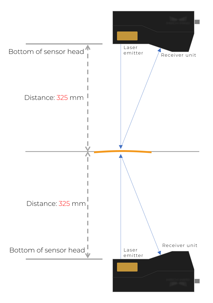
Positions of the sensor heads: The sensor heads of the two laser profilers should be mounted perpendicular to the front and back sides of the bent plate, respectively, 325 mm away from each side. Ensure that each acquisition covers the entire bent plate. If some areas of the target are difficult to capture completely, you can tilt the corresponding sensor head slightly to ensure the acquired image is clear and accurate.
-
Mounting method: Securely mount the sensor head with a bracket.
For more information on mounting, see Mounting and Connection.
-
Prepare a Calibration Target
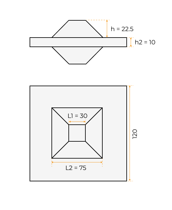
To accurately stitch the surface data scanned by the two laser profilers into a reference frame, the two devices need to be calibrated. For calibration target preparation, see Design and Machine the Calibration Target.
The dimensions of the calibration target used in this example are as follows (unit: mm):
Software Installation
The 3D measurement system mainly involves the following software products:
-
Mech-Eye Viewer software (included in Mech-Eye SDK)
-
Mech-MSR 3D measurement and inspection software
Please visit the Download Center to obtain the latest versions of the software.
| It is recommended to use Mech-MSR 2.2.1 with Mech-Eye Viewer2.6.0 or above. |
Laser Profiler Calibration
After connecting to each laser profiler in Mech-Eye Viewer, adjusting parameters and obtaining high-quality image data, you can perform laser profiler calibration in Mech-MSR.
-
See Adjust Parameters to learn how to adjust the parameters in Mech-Eye Viewer and obtain image data that satisfies the requirements.
-
See Preparations and Calibrate a Single Group to learn how to calibrate two laser profilers in an opposite layout in Mech-MSR.
After calibration, you should save the calibration results. The calibration result is the calibration parameter group of the laser profilers, which is saved in the calibration folder in the project directory.
Connect the Laser Profilers to Acquire Data
-
Connect the laser profilers in Mech-Eye Viewer.
Open the Mech-Eye Viewer software, find each device to be connected, and click the Connect button.
-
Acquire and view data.
Each laser profiler obtains data by scanning an object line by line. For every line scan, a profile can be obtained, and profiles of all lines can be combined to generate an intensity image and a depth map.
See Acquire and View Data to learn how to use Mech-Eye Viewer to acquire high-quality data.
-
The models, IDs, and ROI settings of laser profilers should be consistent with those during calibration.
-
Ensure that grouped laser profilers have identical trigger settings (with the exception of trigger delay) and resolution settings.
- Tuning experience
-
-
Adjust the Exposure Time parameter to make sure the gray values of the target regions all fall within the range of 200–255. Underexposure may result in point cloud loss, while overexposure can lead to excessive flying points.
-
Perform multiple scans to ensure that the acquired image data is complete and free of prominent point cloud loss.
-
-
-
Connect to each laser profiler in the Mech-MSR software.
Click the 3D Laser Profiler Step. In the parameter configuration panel, set Camera Mode to Multiple and select the corresponding option from Calibration Parameter Group of Laser Profilers. The information of the devices used under Camera Info will then be automatically updated.
In this example, virtual device data is used, so Virtual Mode is enabled. See the 3D Laser Profiler Step for detailed instructions. -
Obtain image data.
In the graphical programming workspace of Mech-MSR, click the single-run icon
 on the Step card of the 3D Laser Profiler Step to trigger data acquisition. In this way, the image data can be obtained.
Next, you can continue processing image data in the Mech-MSR software.