Configure TCP ASCII Communication in Mech-MSR
Mech-Mind’s 3D measurement system can communicate with an external device via TCP ASCII communication.
Configuration Process
Follow these steps to configure the TCP ASCII communication:
-
On the toolbar of the software, click the Communication Configuration button.
-
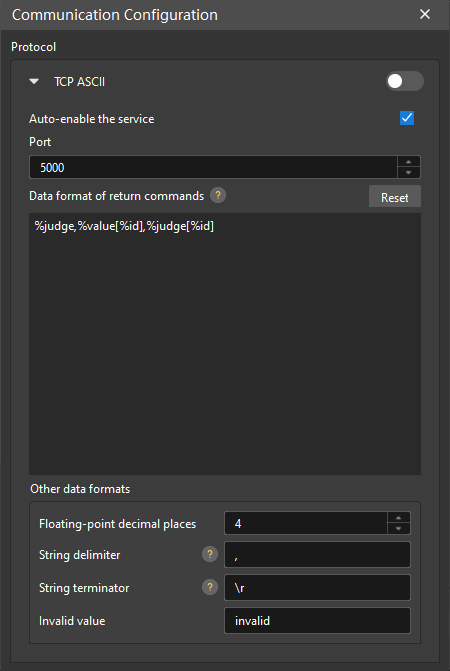
Click the ▶ icon next to TCP ASCII protocol to expand the settings.
-
Set Port parameter based on your needs.
The default value of the Port parameter is 50000. After the TCP ASCII communication service is enabled, the software listens to TCP ASCII commands sent by external devices at the specified port.
-
(Optional) Refer to the Data format of return commands setting instructions to configure the Data format of return commands parameter.
The Data format of return commands parameter is used to customize the format of the data returned by the software to the return and execute commands.
To have the system automatically push results to the client in the configured return command data format after each project run, you can select the Auto-push results option. For more information, refer to Communication Workflow (Command-Free). -
(Optional) Set other data formats by referring to Set Other Data Formats.
If you want the TCP ASCII communication service to be auto-enabled the next time you open the solution, you can select the Auto-enable the service option.
|
Set Data Format of Return Commands
After a return command or execute command is sent by an external device, the software can return results according to the specified Data format of return commands.
Supported Data Formats
The returned data for the return command supports the following fields. You can combine them according to your needs.
| Field | Description |
|---|---|
|
Image acquisition time in the format of 20200101010101100 (01:01:01 sec, 100 ms, 01/01/2020). |
|
The overall quality judgment result of the project. |
|
The measured value of the specified measurement item. For example, |
|
The measured values of all configured measurement items in the Communication output tab. |
|
The judgment result of the specified measurement item. For example, |
|
The judgment results of all configured measurement items in the Communication output tab. |
|
The ID of the project. |
Measured Value and Judgment Result
Measured value of a measurement item
Mech-MSR will return measured values to an external device only if the following conditions are met:
-
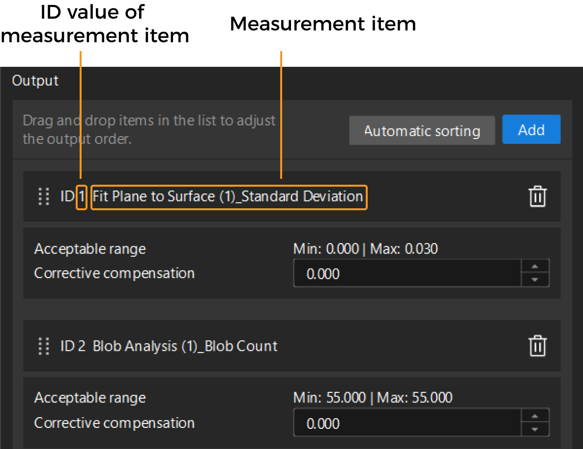
In the Communication output tab of Mech-MSR’s Output Management window, the measurement item has been added to the Output area. The ascending order of ID values of measurement items is the order of returned results.
-
In the Communication Configuration window, the value of the Data format of return commands parameter contains either “%value[%id]” or “%value[ID value of the measurement item]”.
Judgment result of a measurement item
For the judgement result of a measurement item, 1 stands for OK, and 0 for NG. Mech-MSR will return the judgment result to an external device only if the following conditions are met:
-
In the Communication output tab of Mech-MSR’s Output Management window, the measurement item has been added to the Output area. The ascending order of ID values of measurement items is the order of returned results.
-
In the Communication Configuration window, the value of the Data format of return commands parameter contains either “%judge[%id]” or “%judge[ID of the measurement item]”.
Example
Suppose that the Communication output tab contains three measurement items, whose IDs are 1, 2, and 3.
| Example | Description | |
|---|---|---|
1 |
Data format |
%judge, %value[%id], %judge[%id] |
Returned result |
0, 100, 0, 200, 0, 300, 0 |
|
Mapping relationship |
%judge, %value[1], %judge[1], %value[2], %judge[2], %value[3], %judge[3] |
|
2 |
Data format |
%judge, M%id, %value[%id], %judge[%id] |
Returned result |
0, M1, 100, 0, M2, 200, 0, M3, 300, 0 |
|
Mapping relationship |
%judge, M1, %value[1], %judge[1], M2, %value[2], %judge[2], M3, %value[3], %judge[3] |
|
3 |
Data format |
%judge, V%value[%id], J%judge[%id] |
Returned result |
0, V100, J0, V200, J0, V300, J0 |
|
Mapping relationship |
%judge, V%value[1], J%judge[1], V%value[2], J%judge[2], V%value[3], J%judge[3] |
|
| Examples 2 and 3 are examples of adding character prefixes. In example 2, M%id stitches the character M together with the ID of the measurement item in the output. In example 3, V%value[%id] and J%judge[%id] add the characters V and J before the measured value and judgment result of each measurement item respectively. |
Set Other Data Formats
You can set other data formats according to your needs.
| Parameter | Description |
|---|---|
Floating-point decimal places |
Specifies the number of decimal places to keep when the software outputs the measured values. The value ranges from 0 to 20. The default value is 4. |
String delimiter |
Specifies the delimiter used to separate data (between command name and parameter, and between parameters) in TCP command requests. Common string delimiters include the English comma (,) and semicolon (;). By default, the string delimiter is the English comma. |
String terminator |
Specifies the string terminator of commands. Common string terminators are \n and \r. By default, the terminator is \r. |
Invalid value |
Specifies the data format when there are no measured values or no judgment results. The default value is “invalid”. |
General Parameter
Execution timeout period for return command
The maximum timeout period from the external device sending the return command to the external device receiving a valid response or triggering a timeout error. The default value is 10 seconds.