Start Measurement
After data processing, you can use the data to measure the track’s width, height, cross-sectional area, and offset and thus judge whether the applied beads are up to standard.
Measurement Workflow
You can use the Measure Surface Track Step to conduct all measurement tasks of beads.
The detailed instructions are as follows:
-
In the Track Line Editor, define an ideal path for applied beads, i.e., a track line.
-
In the parameter configuration panel of the Measure Surface Track Step, click the Open the editor button to open the editor window.
-
Create a track line file and draw a track line. The drawn track line will be used as the centerline of the applied beads and the points on the line will be compared with the measured center points to calculate the offset. See Usage Workflow for operational instructions.
-
Configure Section Profile Settings for high-quality section profiles of beads.
-
Click the Save button to save all settings. Then, you can close the editor and return to the software’s home interface.

- Tuning experience
-
-
Appropriately adjust the Length and Width parameters to ensure that the obtained section profiles can fully reflect the cross-section characteristics of the applied beads and include some surrounding surface data.
-
A smaller Interval can lead to more section profiles and more detailed detection.
-
-
-
Set relevant parameters in the parameter configuration panel of the Measure Surface Track Step.
-
Select a track line file from the drop-down list under Track Line Settings.
-
Configure Detection Settings. In the example project, most parameters keep their default values. The adjustments are as follows:
-
Select the Use Median Filter option and set the window size to 0.300 for smoother profiles.
-
Set the Gap Filling Threshold to 0.200 to fill the gaps in section profiles.
-
Keep the default value of 0.200 of the Peak Detection Threshold to detect the peak points of each profile for track height calculation.
-
Set the Side Height Threshold to 0.400 to detect the side points from each profile for track width and center point calculation.
-
-
Configure Judgment Settings.
Set the nominal values of width, height, cross-sectional area, and offset, as well as their respective tolerances. Only section profiles that meet all judgment parameter settings can be considered qualified (OK).
Set the parameter according to the actual design requirements. -
(Optional) Configure display settings.
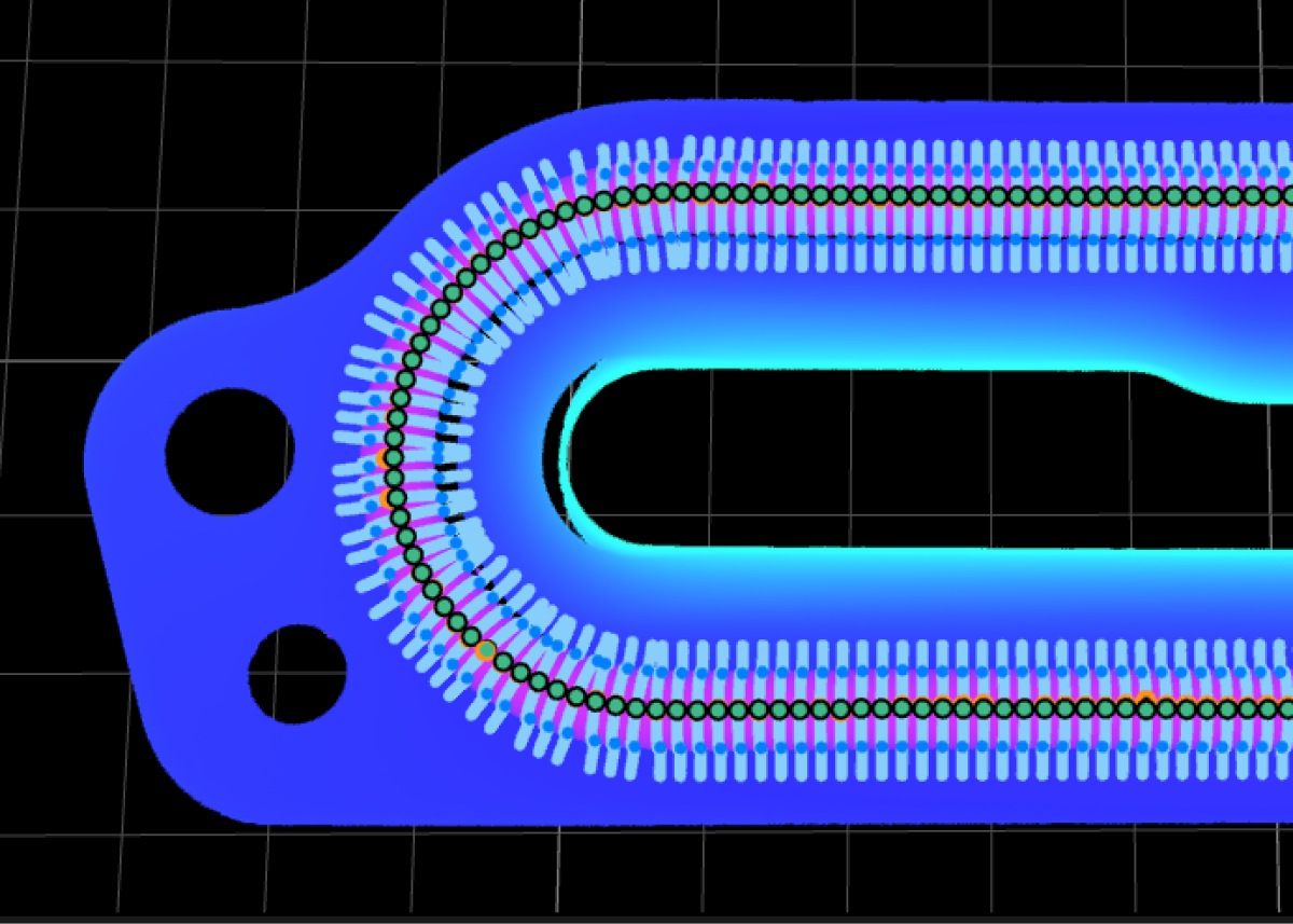
It is recommended to select the Show Measured Results option. After the Step is run, you can intuitively view the running results in the data visualization area.

-
In the Output section, select output items according to actual needs. Since the example project is designed to inspect whether all applied beads are OK, only the NG Count item is selected to output the number of section profiles that do not meet the standards.
-
After the configuration, you can run the Step to obtain the measured results. You can view the running results in real time in Output Results panel below the data visualization area.
Next, you can set an acceptable range for the measurement item to obtain the inspection result.