Design 3D Measurement and Inspection Solution
Before actual deployment, you need to design a 3D measurement and inspection solution first, including selecting the laser profiler model, the IPC model, the laser profiler mounting method, and the communication method according to the actual requirements of the project.
In this phase, you need to complete:
Select the Laser Profiler Model
Familiarize yourself with the laser profiler models, their characteristics and applicable scenarios according to Laser Profiler Models, and select the appropriate laser profiler model according to the actual requirements of the project.
Please follow the procedure below to select the laser profiler model:
-
Determine the laser profiler model based on the measured object’s dimensions (length, width, and height).
Selection basis: The X-axis measurement range of the laser profiler should be larger than the length or width of the object to be measured. Usually, the long side of the laser profiler is parallel to the long side of the object to be measured, and the X-axis measurement range is larger than the width of the object to be measured. In addition, the Z-axis measurement range of the laser profiler should be larger than the height of the object to be measured.
If multiple models of laser profilers meet your requirements, it is recommended to choose the model with a smaller measurement range.
If the long side of the laser profiler is parallel to the wide side of the object to be measured, the X-axis measurement range should be larger than the length of the object to be measured. If two or more objects are stitched together for measurement, the X-axis measurement range should be greater than the total length or width of the objects after stitching. 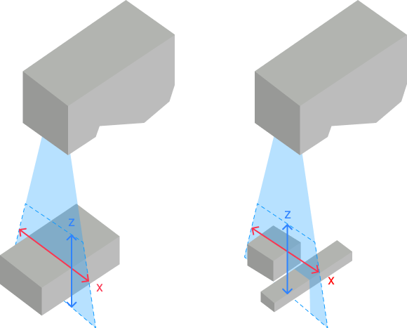
-
Confirm that the laser profiler accuracy meets the project accuracy requirements.
The X-axis resolution and Y-axis resolution of the laser profiler should be smaller than the resolution required by the project.
The resolution reflects the minimum size or amount of variation that the laser profiler can resolve. Usually, the higher the laser profiler resolution (the smaller the value), the more accurate the laser profiler.
Usually, in a depth map, the measurement region should consist of at least 5 × 5 to 10 × 10 pixels. You can calculate the X-axis and Y-axis resolution requirements on the basis of the smallest measurement region. For example, if the measurement region is 1 mm × 1 mm, and 10 × 10 pixels are used to represent the region, each pixel should correspond to an actual area of 0.1 mm × 0.1 mm. In other words, the X-axis and Y-axis resolutions in the depth map output by the laser profiler should be less than 0.1 mm. -
Confirm that the scan rate of the laser profiler meets the project cycle time requirement.
The required scan rate of the project can be calculated using the following equation:
Scan rate = Total scan length / Allowable scan time / Y-axis resolution
For example, if the total scan length is 160 mm, the scan time is 2 s, and the Y-axis resolution is 0.0235 mm, then the needed scan rate of the project is 3.405 kHz.
The above scan rate is only the image acquisition rate of the laser profiler. In actual projects, project processing time and signal/data transmission time should also be considered.
Select the IPC Model
Mech-Mind IPC STD and Mech-Mind IPC ADV models are recommended for 3D measurement and inspection solutions. Please select the appropriate IPC model according to the technical specifications of the IPC and the actual needs of the project.
| Technical specification | Mech-Mind IPC STD | Mech-Mind IPC ADV |
|---|---|---|
Number of Mech-MSR projects that can run simultaneously |
≤3 |
≤5 |
Number of laser profilers that can be connected simultaneously |
≤3 |
≤5 |
| When the image or point cloud data of the target object is large (for example, the number of scan lines is close to 20,000) and the surface features are rich, it will place higher requirements on the performance of the IPC if multiple “Blob Analysis” and “Process Surface by Filter” Steps are required in the same project. Therefore, it is recommended to use the Mech-Mind IPC PRO model to ensure more efficient processing. |
If you need visualized display and tuning when using the Mech-MSR software (i.e., enable Debug Output), please select an appropriate IPC according to the data volume of images or point clouds in the actual project for better user experience:
-
If the number of points is not greater than 1.0 × 10⁷: The Mech-Mind IPC STD series generally meets the requirements.
-
If the number of points is within 1.0–8.0 × 10 7: The Mech-Mind IPC ADV series provides better user experience.
-
If the number of points exceeds 8.0 × 10⁷: The Mech-Mind IPC PRO series delivers the best user experience.
| Even if the number of points in the image or point cloud is within the processing capacity of the selected IPC, enabling Debug Output may still cause lag when using the Mech-MSR software due to high system resource usage. If a severe lag occurs, it is recommended to increase the degree of downsampling. |
Mech-Mind allows you to use your own computer or laptop (“non-standard IPC” for short) as the IPC for installing and running Mech-Mind’s software products. Please note that Mech-Mind does not guarantee that the functions and performance of a non-standard IPC are the same as those of a standard IPC. Your own IPC should meet the system requirements for installing the Mech-MSR software.
Select the Laser Profiler Mounting Method
The sensor head of the laser profiler needs to maintain its relative movement with the target object while acquiring data. You can choose any of the following methods according to the actual layout of the production line:
-
Fix the sensor head and move the target object: The sensor head needs to be securely mounted on a fixed bracket.
-
Fix the target object and move the sensor head: The sensor head needs to be securely mounted on the frame of the motion mechanism.
| The sensor head generates a great amount of heat during continuous data acquisition. If the sensor head cannot dissipate this heat effectively, the resulting excessively high temperature may cause it to malfunction. See Heat–Dissipation Measures for Laser Profiler to evaluate the heat–dissipation conditions on site before mounting the sensor head. |
The sensor head can be mounted in two ways:
-
Side mounting (recommended)

-
Top mounting
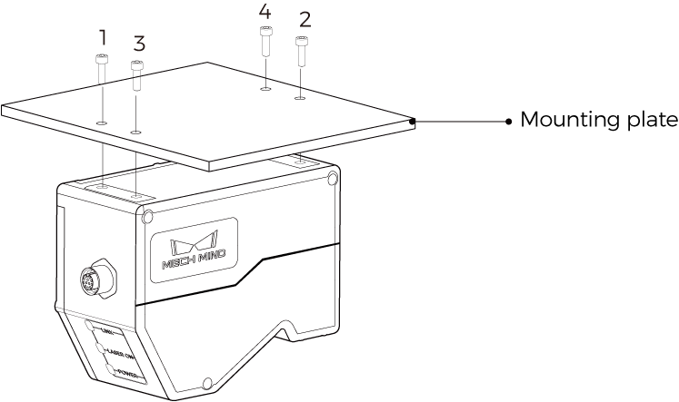
Please select the mounting method according to the actual needs of the project. For instructions on mounting the laser profiler, refer to Mounting and Connection.
Select the Laser Profiler Triggering Method
The laser profiler supports multiple methods to trigger data acquisition. The laser profiler supports controlling the triggering method of each round of data acquisition and each line scan separately.
There are two methods each for triggering one round of data acquisition and one line scan.
-
Trigger a round of data acquisition:
-
External: Use the signal input from an external device to trigger each round of data acquisition.
-
Software: Use Mech-MSR, Mech-Eye Viewer, Mech-Eye API, or a GenICam client to trigger each round of data acquisition. In a 3D measurement and inspection solution, the “Software” method refers to triggering each round of data acquisition by Mech-MSR.
-
-
Trigger a line scan:
-
Encoder: Use encoder signals to trigger each line scan.
-
Fixed rate: Trigger each line scan at a fixed rate.
-
Laser profilers support the following combinations of triggering methods. Please select the appropriate combination of triggering methods according to Combination of Triggering Methods and the actual needs of the project.
| External | Software | |
|---|---|---|
Encoder |
||
Fixed rate |
Select the Communication Mode
In a 3D measurement and inspection solution,Mech-MSR needs to send the measurement or inspection result of the project to an external device.
The communication modes currently supported by Mech-MSR are as follows:
-
TCP ASCII
-
EtherNet/IP
-
PROFINET
-
Modbus TCP
-
Siemens S7 Client
-
Mitsubishi MELSEC Client
-
Adapter
| To ensure that the Mech-MSR can communicate normally with an external device, make sure that the external device supports the selected communication mode. |