Data Processing
Adjust Applied Beads to Horizontal Level
Bead inspection involves multiple measurement tasks, such as the height, width, and cross-sectional area of adhesive beads. If the applied beads are tilted in the acquired data, it is difficult to select the target surface data and use depth information (Z values) for data filtering. For accurate measurements in subsequent processes, the beads must be adjusted to a horizontal level (parallel to the XOY plane). You can use the Transform Surface Step to transform the reference frame of the surface data and thus make the applied beads horizontal.
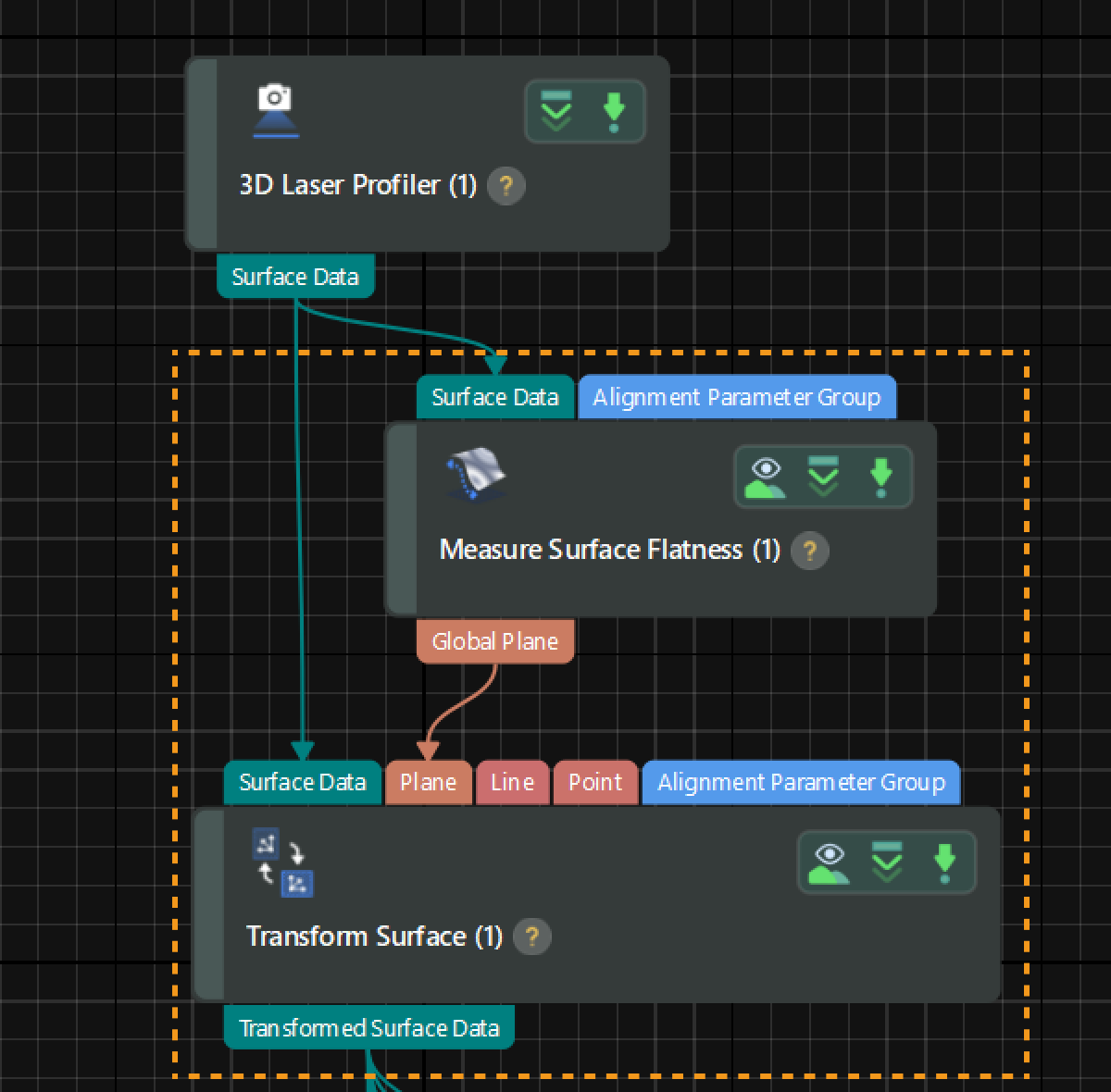
Since beads are applied on a flat surface, adjusting the application surface to a horizontal level can level the applied beads. In this case, you can use the Transform Surface Step to transform the surface data to a new reference frame by the Plane method.
The detailed instructions are as follows:
-
Extract a plane feature: Use the Measure Surface Flatness Step to obtain a plane feature, which will be taken as the XOY plane of the new reference frame.
Select the Step and adjust the feature regions in the data visualization area to include the flat surface data around beads for plane fitting.
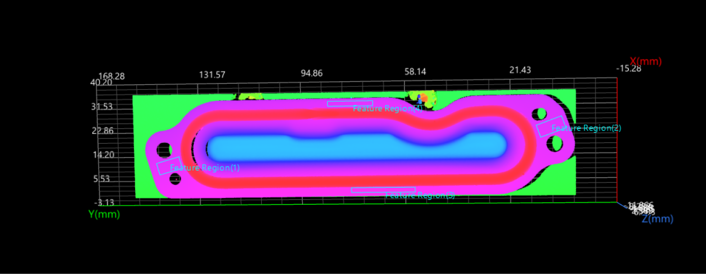
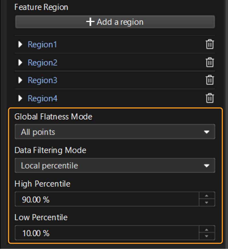
Then, set parameters related to plane fitting and data filtering in the parameter configuration panel, as shown in the figure below.
-
Transform the reference frame: Input the fitted plane into the Transform Surface Step and run the Step to transform the surface data to the new reference frame. At this time, the applied beads have been adjusted to a horizontal level; the X-axis of the new reference frame is parallel to the original one, and the origin is the projection of the origin of the original reference frame on the new XOY plane.
-
In the Output Results panel, click
 or
or  to switch the data visualization status, and the data viewer will display the visual content accordingly.
- Tuning experience
-
-
Both the Fit Plane to Surface Step and the Measure Surface Flatness Step can be used to rapidly fit a plane, but you can remove noise in data by the latter to obtain a more accurately fitted plane.
-
The running speed of the Transform Surface Step is affected by the Scan Line Count parameter set in Mech-Eye Viewer. When the parameter value is large, the image processing speed of the Step will slow down, which is likely to increase the cycle time.
-
-
Data Alignment
During different scans of target objects, the object position in the acquired image data may vary slightly. You can extract common features to align different images and ensure consistency in subsequent measurements. On the basis of the above surface data transformation, you can use another Transform Surface Step to align data.
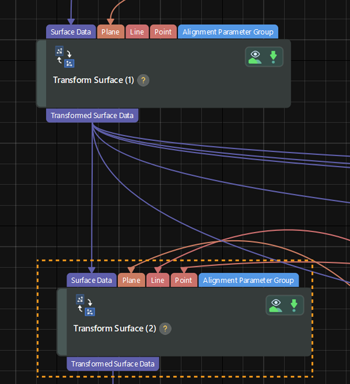
You can transform the reference frame to accurately position the target object at a fixed location by the Plane + Line + Point method. In this case, you need to extract the plane, line, and point features separately.
As required by the user, the location of the target object in the image following the reference frame transformation should be as follows:
-
The flat surface surrounding the applied beads should be on the XOY plane.
-
The center of the reference hole should be at the origin.
-
The line connecting the center of the reference hole and the center of the oval hole can be rotated 9° clockwise around the center of the reference hole to coincide with the X-axis of the new reference frame.
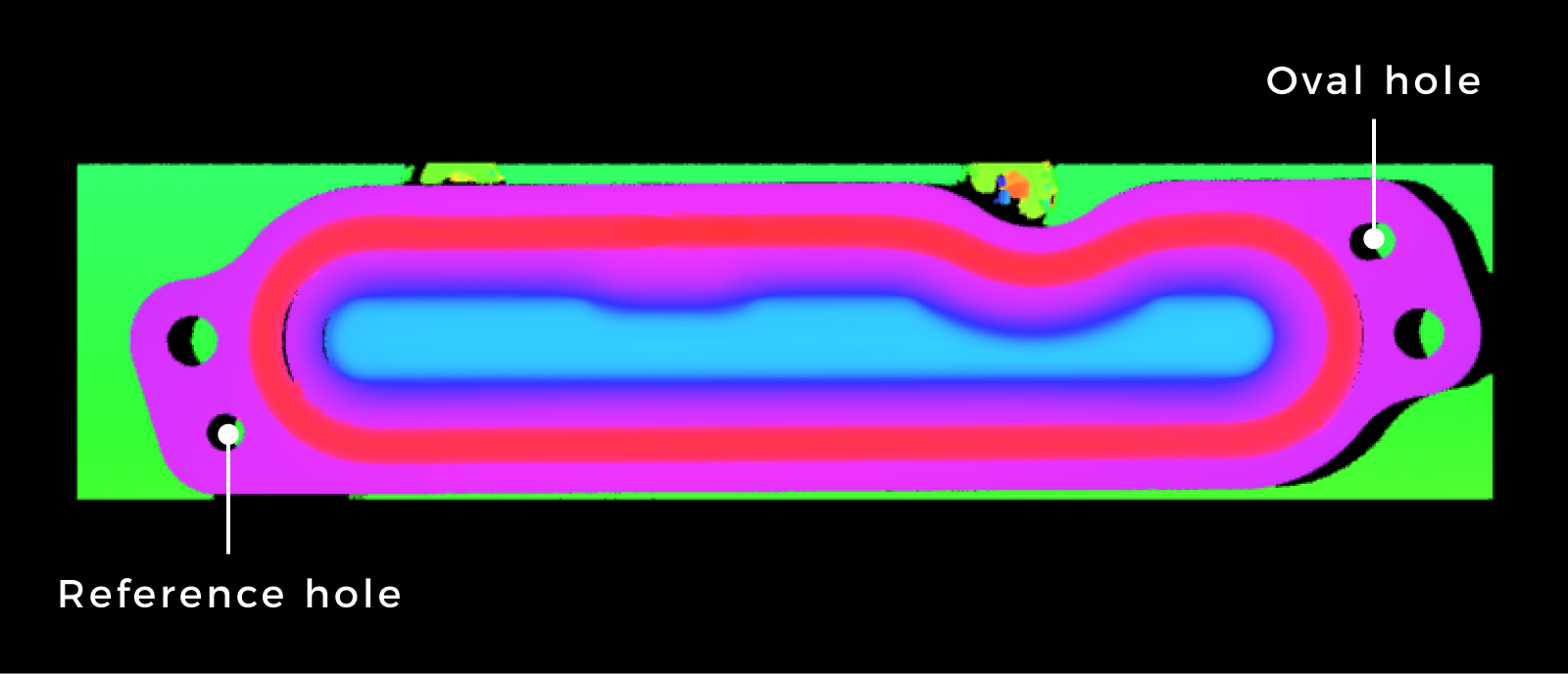
Next, you need to obtain the geometric features required for transforming surface data step by step.
-
Extract a plane feature
You can use the Create Plane from Features Step to obtain a plane feature. Following the Adjust Applied Beads to Horizontal process, the flat surface surrounding the applied beads is the XOY plane. Thus, keep the XOY plane unchanged.
The parameter configuration process of the Step is as follows:
-
Set the Plane Type to Constant plane.
-
Set the plane’s Normal Z to 1 (or another value) and leave the remaining parameters at their default value of 0.
-
Verify the Created Plane option is selected in the Output section of the Step.
After the Step is run, it will output the created plane, which coincides with the XOY plane of the original reference frame.
-
-
Extract a point feature
You can use the Fit Circle to Surface Edge Step to fit a circle to the reference hole data and obtain the hole center.
The parameter configuration process of the Step is as follows:
-
Select the Use Feature Region option to include surface data of the reference hole, and the size and position of the circular path will be determined accordingly.
-
Configure settings related to calipers. It is recommended that the set Angle Span, Caliper Count, Caliper Length, and Caliper Width ensure the detected edge points evenly cover the entire circular edge.
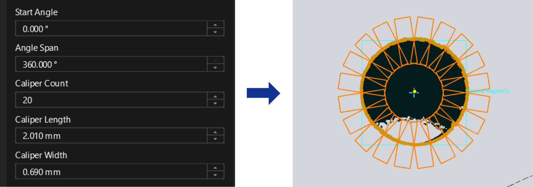
-
Set the Null Filling Value of Depth to -2.700. Setting a value that is clearly different from the plane where the edge lies can help detect the ideal edge points.
-
Select Last from the drop-down list of Step Type and set the Absolute Threshold to 1.000. The settings can be used to accurately obtain target edge points.
-
In the Output section of the Step, verify that the Center of Fitted Circle item is selected.
After the Step is run, it will output the hole center, which can be used as the origin of the new reference frame.
-
-
Extract a line feature
As specified, the line connecting the center of the reference hole and the center of the oval hole can be rotated 9° clockwise around the center of the reference hole to coincide with the X-axis of the new reference frame. To acquire the line connecting the two hole centers, first, find the center of the oval hole.
Method for obtaining the center of the oval hole: Use two Fit Circle to Surface Edge Steps to fit circles to two halves of the oval hole and thereby obtain two hole centers. Then, use the Create Point from Features Step to calculate the midpoint from the two hole centers and thus obtain the center of the oval hole.
The detailed instructions are as follows:
-
Use two Fit Circle to Surface Edge Steps to fit respective circles to the two halves of the oval hole.
-
Select the Use Feature Region option to include half the surface data of the oval hole, and the size and position of the circular path will be determined accordingly. Be sure to expand Region1 and set the feature region’s Rotation Angle to 9°.
-
Configure settings related to calipers. It is recommended that the set Angle Span, Caliper Count, Caliper Length, and Caliper Width ensure the detected edge points evenly cover the entire circular edge.
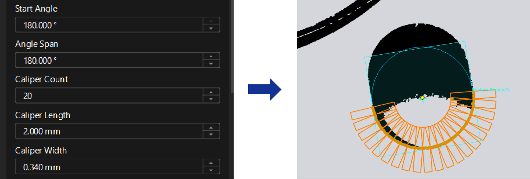
-
Set the Null Filling Value of Depth to -2.700. Setting a value that is clearly different from the plane where the edge lies can help detect the ideal edge points.
-
For the upper half, select First from the drop-down list of Step Type and set the Absolute Threshold to 1.000; for the lower half, use the default settings.
-
In the Output section of the Step, verify that the Center of Fitted Circle item is selected.
After the two Steps are run, they will output the centers of half holes separately.
-
-
Input the two hole centers to a Create Point from Features Step. In the parameter configuration panel of the Step, set the Point Type to Midpoint from two points to obtain the center of the oval hole.
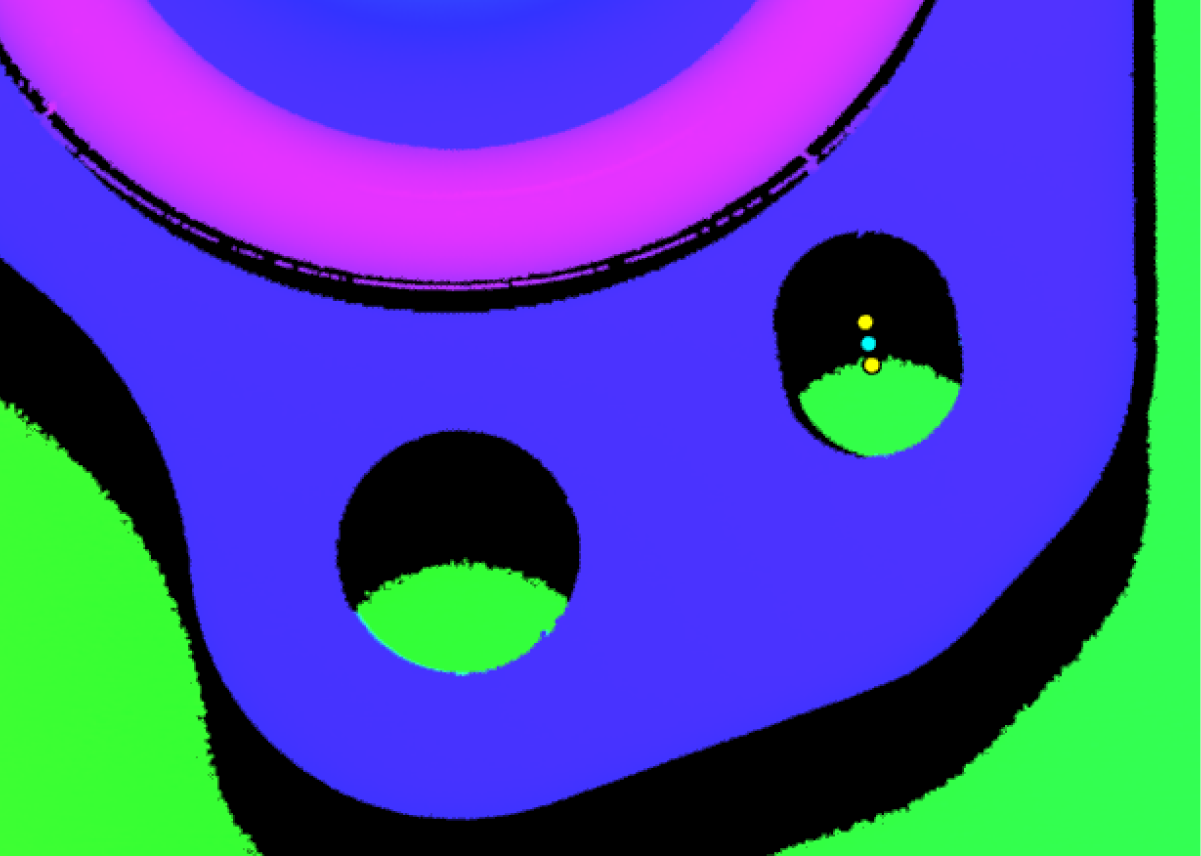
-
Then, use the Create Line from Features Step to connect the center of the reference hole with the center of the oval hole to obtain a line.
-
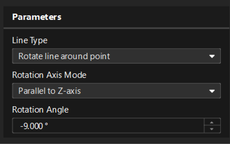
Input the obtained line and the center of the reference hole into another Create Line from Features Step and configure the parameters to rotate the line 9° clockwise around the center of the reference hole.
The parameter configuration of this Step is shown below.
-
In the Output section of the Step, verify that the Created Line option is selected.
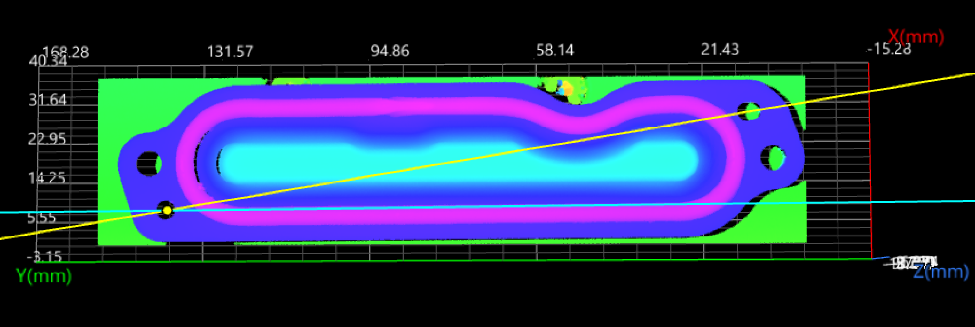
After the Step is run, it will output the rotated line. The line should coincide with the X-axis of the new reference frame.
-
-
Data Alignment
Input the extracted plane, point, and line features into the Transform Surface Step. The parameter configuration process of the Step is as follows:
-
Select the Use Feature Region option to include the surface data with applied beads and the flat surface surrounding them to narrow down the data range.
-
In the drop-down list of Resolution Mode, select Original.
After the Step is run, it will output the transformed surface data. At this time, the image data has been aligned.
-

Data Filtering
Use the Filter Surface Points by Normals Step to filter the aligned surface data and remove noise in the data.
-
Parameter settings: In the parameter configuration panel of the Step, set the Max Polar Angle to 80° and keep the default settings of other parameters.
After the Step is run, it will output the filtered surface data.
Next, you can use the processed data to measure and inspect the track.