Measure Feature Point Height
Description
This Step is used to locate the feature point(s) of the profile and measure the height of feature point(s) relative to a reference line or a base point.
Workflow
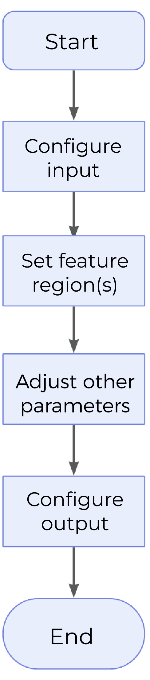
The process of configuring this Step is as follows:
-
Configure the input. Connect the ports manually or select the input(s) under Input in the parameter configuration panel.
-
Set the feature region.
-
Set other parameters.
-
Select the desired output items under Output. For an expandable output item, click ▶ and configure the Lower Limit and Upper Limit values to set the acceptable range.
Parameter Description
| Parameter | Description | ||
|---|---|---|---|
Feature Region |
This parameter is used to add feature regions (1–64) for locating feature points on the profile.
|
||
Reference Line |
When this parameter is selected, a reference line will be fitted using the data within the line region(s).
|
||
Use Base Point |
This parameter defines a region for locating a base point, which facilitates the measurement of feature point height.
|
Height Measurement Method
There are four ways to measure feature point height, corresponding to the following four calculation methods. You can choose among them according to the actual measurement requirements.
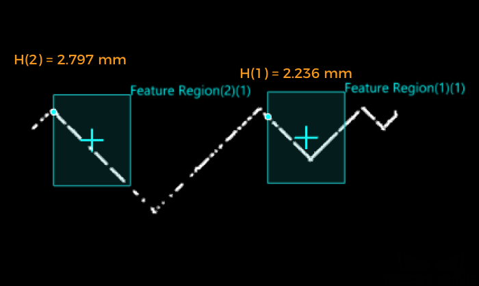
- Feature Region Only
-
It is possible to set 1–64 feature region(s), and the 1–64 feature point height(s) can be measured at once. In this case, take the line with Z = 0 as the reference line, and calculate the distance from the feature point to this line as the feature point height. The height is positive for points above the line and negative for points below the line.
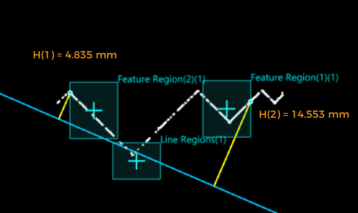
- Feature Region + Reference Line
-
Calculate the distance from the feature point to the reference line as the feature point height. The height is positive for points above the line and negative for points below the line.
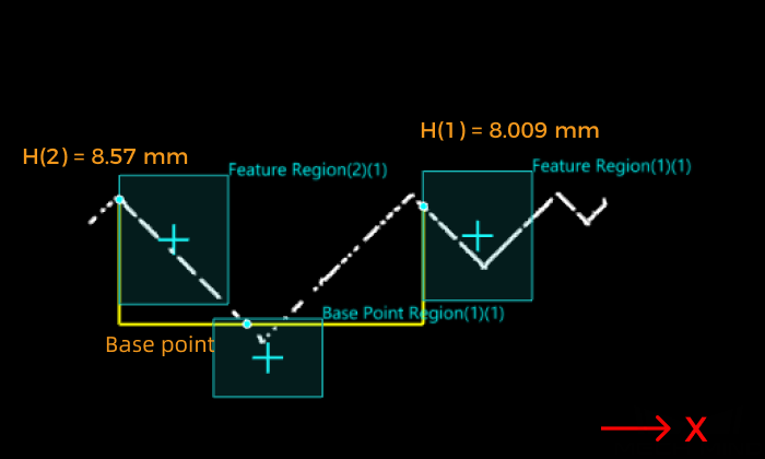
- Feature Region + Base Point
-
Make a reference line parallel to the X-axis through the base point, and calculate the distance from the feature point to the line. The height is positive for points above the line and negative for points below the line.
In this case, the base point height is the distance from the base point to the line with Z = 0.
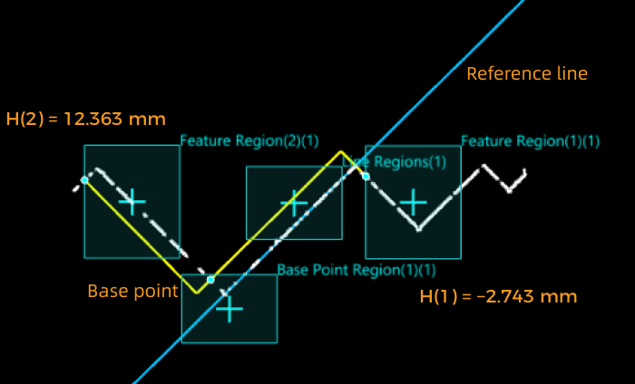
- Feature Region + Reference Line + Base Point
-
Make a line parallel to the reference line through the base point, and calculate the distance from the feature point to the line. The height is positive for points above the line and negative for points below the line.
In this case, the base point height is the distance from the base point to the reference line.
Output Description
Select the output item(s) to add the output port(s) to the Step, and the corresponding data will be output after the Step is run. You can select the output according to the actual measurement requirements.
|
If you select an expandable output item, you must expand it by clicking ▶, and then set the Lower Limit and Upper Limit values to determine the acceptable range. If the output value of the measurement item falls within the acceptable range, it is judged as okay (OK), or else it is judged as not good (NG). |
| Output Item | Description |
|---|---|
Height of Feature Point |
The height of a feature point to the reference line or that of a feature point to the base point. The height is positive for feature points above the reference line or base point, and negative for feature points below the reference line or base point.
|
Height of Base Point |
Without reference line, the base point height is the distance from the base point to the line with Z = 0.
|
Troubleshooting
|
CV-W5701
Error: The selected feature point type is invalid.
Solution: Select a valid feature point type in the “Feature Point Type” drop-down list.
CV-W5702
Error: The value of “Low Percentile” should not be greater than that of “High Percentile,” or either of them is not within [0, 1].
Possible cause: The value of “Low Percentile” is greater than that of “High Percentile,” or either of them is not within 0–100%.
Solution: Reset the percentile to ensure that the percentile is within 0–100% and that the value of “Low Percentile” is lower than that of “High Percentile.”
CV-W5703
Error: The “Outlier Fraction” value is not within [0, 1].
Possible cause: The set outlier fraction is not within 0–100%.
Solution: Reset “Outlier Fraction” to ensure that the value is within 0–100%.
CV-W5704
Error: Failed to fit a circle as data points in Region2 are insufficient.
Possible cause: The number of points in Region2 is smaller than 3, which leads to the failure of circle fitting.
Solution: Adjust the feature region to ensure that the number of points in Region2 is equal to or greater than 3.
CV-W5705
Error: No contact point is detected as the fitted line and circle are separated.
Possible cause: The fitted line and circle are separated.
Solution: Adjust the feature region to ensure that the fitted line and circle intersect or are tangent.
CV-W5706
Error: Failed to fit a line as data points in Region2 are insufficient.
Possible cause: The number of points in Region2 is smaller than 2, which leads to the failure of line fitting.
Solution: Adjust the feature region to ensure that the number of points in Region2 is equal to or greater than 2.
CV-W5707
Error: Failed to detect an intersection point as the two lines are parallel.
Possible cause: The two lines are parallel.
Solution: Adjust the feature regions to ensure that the fit two lines can intersect.
CV-W5708
Error: Failed to detect a feature point of inflection.
Possible causes:
-
The “Sensitivity” value is too small.
-
The “Inflection Type” was not selected properly.
-
The profile in the feature region is too flat, and there is no point of inflection.
Solution:
-
Increase the value of “Sensitivity” appropriately.
-
Select a valid “Inflection Type.”
-
Reset the feature region to ensure that at least a valid point of inflection can be generated.
CV-W5709
Error: The set “Index” value is out of range.
Solution: Adjust the “Index” value to ensure that it is no greater than the number of turning points.
CV-W5710
Error: Insufficient data points defined by reference region(s).
Possible cause: When the “Reference Line” is selected, the number of points in the line region(s) is smaller than 2, which leads to the failure of line fitting.
Solution: Adjust the line region(s) to ensure that the number of points in the region is greater than or equal to 2.