Detect and Measure Hole on Surface
Description
This Step is used to detect the hole on a surface and output the location and radius of the detected hole.
Usage Scenario
Quality inspection, equipment calibration, object recognition, and positioning can be performed by locating and measuring holes on the surface of the workpiece.
Workflow
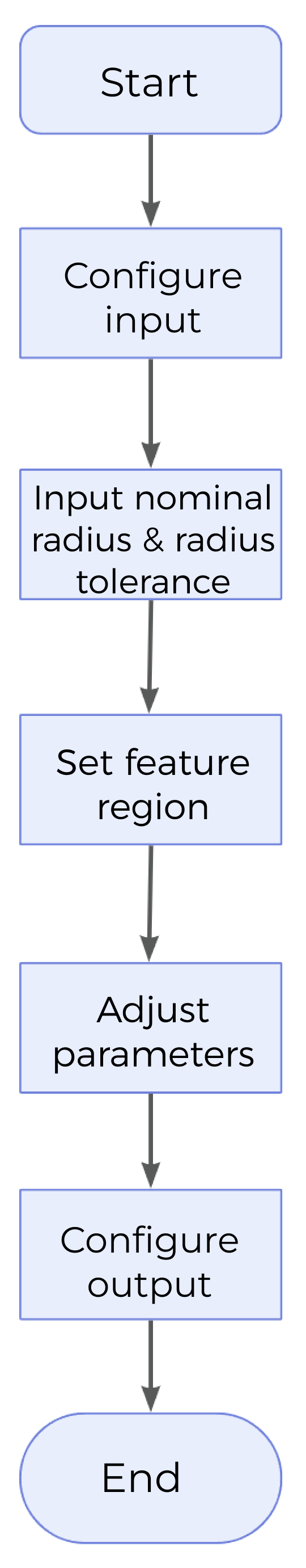
The process of configuring this Step is as follows:
-
Configure the input. Connect the ports manually or select the input(s) under Input in the parameter configuration panel.
-
Set Nominal Radius and Radius Tolerance under Parameters.
-
Configure the feature region and reference plane (optional).
-
Select the desired output items under Output. For an expandable output item, click ▶ and configure the Lower Limit and Upper Limit values to set the acceptable range.
Input Description
| Parameter | Description |
|---|---|
Surface Data |
Image data in MRAW format, usually including a depth map and an intensity image. |
Alignment Parameter Group |
Optional input. The parameter group used for the translation and rotation of the feature region(s). For more information, see Alignment Parameter Group. |
Reference Plane |
Optional input. After a reference plane is input, the detected circular hole will be on this plane. When the surface near the target hole is not flat, it is recommended to use a reference plane. Meanwhile, the Step supports the custom reference plane. You can select Use Custom Plane as Reference in the Parameters section. For details, refer to Parameter Description. |
Parameter Description
| Parameter | Description | ||
|---|---|---|---|
Nominal Radius |
The expected radius of the hole, i.e. the standard radius of the hole. |
||
Radius Tolerance |
The allowable maximum variation of measured radius from the nominal radius (+ / - from the nominal radius). |
||
Use Local Detection |
The center of the hole to be detected must be within the feature region. For Use Local Detection to be selected, this condition must be met, otherwise no measurement can be performed effectively.
|
||
Use Depth Limit |
Once this option is selected, set Depth Threshold for data points. Points with depth values (relative to the measurement plane or reference plane) above the set threshold will be removed from hole calculation. |
||
Feature Region |
Configure the feature region to ensure that the hole to be detected is within the feature region. For more information on how to set and adjust the feature region, see Feature Region.
|
||
Use Custom Plane as Reference |
The surface near the hole may be uneven. In this case, you can set a reference plane so that the detected circular hole is on the reference plane. Once this option is selected, you can set one or two reference feature regions to select the surface data on the same plane as the target hole, and use these data to fit the reference plane so that the detected hole is on the reference plane.
|
Output Description
Select the output item(s) to add the output port(s) to the Step, and the corresponding data will be output after the Step is run. You can select the output according to the actual measurement requirements.
|
If you select an expandable output item, you must expand it by clicking ▶, and then set the Lower Limit and Upper Limit values to determine the acceptable range. If the output value falls within the qualified range, the measurement is judged as passing (OK), or else it is judged as failing (NG). |
| Output Item | Description |
|---|---|
Hole Center X |
The X value of the hole center. |
Hole Center Y |
The Y value of the hole center. |
Hole Center Z |
The Z value of the hole center. |
Radius |
The radius of the hole. |
Hole Center |
The center point of the hole. |
Circle |
The detected circular hole. |
Troubleshooting
|
CV-W3201
Error: Data points defined by the feature region are insufficient.
Solution: Adjust the feature region to ensure that there are enough points.
CV-W3202
Error: Data points defined by the reference region(s) are insufficient.
Solution: Reset the reference region to ensure that there are enough points.
CV-W3203
Error: The set “Nominal Radius” value is unreasonable.
Possible causes: The set nominal radius is too large or too small.
Solution: Reset Nominal Radius appropriately.
CV-W3204
Error: The difference between measured radius and “Nominal Radius” value is too huge.
Solution: Reset Nominal Radius, Radius Tolerance, or adjust the feature region.
CV-W3205
Error: The set “Radius Tolerance” value is unreasonable.
Possible causes: The set radius tolerance is too large or too small.
Solution: Reset Radius Tolerance appropriately.
CV-W3206
Error: No circle detected.
Possible causes:
-
The hole is not included in the feature region.
-
Tilt Correction is not set properly.
Solutions:
-
Adjust the feature region so that the hole is included.
-
Reset Tilt Correction.
CV-W3207
Error: Cannot perform reprojection.
Possible causes:
-
The feature region is not set properly.
-
Tilt Correction is not set properly.
Solutions:
-
Adjust the feature region.
-
Reset Tilt Correction.
CV-W3208
Error: Data points defined by feature region(s) are insufficient.
Possible causes:
-
The set depth threshold is too low.
-
The reference plane is not set properly, i.e., the hole to be measured is not coplanar with the reference plane.
Solutions:
-
Increase the value of Depth Threshold appropriately.
-
Reset the parameters related to the reference plane.