Data Acquisition
Preparation
Select a Laser Profiler and Mount It
-
Select the laser profiler model
For pins of common specifications, it is recommended to use the Mech-Eye LNX-8030-GL laser profiler model. The field of view, accuracy, and measurement range of the device can meet most measurement needs. For detailed technical parameters of the device, see Technical Parameters of LNX-8030-GL.
-
Mounting instructions
-
Position of the sensor head: The sensor head of the laser profiler should be mounted directly above the target object, 78 mm away from the pin tips. Ensure that the sensor head can scan all pins during each acquisition.
-
Pins are usually deep, and surrounding structures may obstruct the sensor head’s view. In this case, you can mover the sensor head horizontally as needed to ensure each pin is clearly visible within the sensor head’s field of view.
-
If certain pins are difficult to capture completely due to their low position, you can tilt the sensor head slightly to ensure the acquired image is clear and accurate.
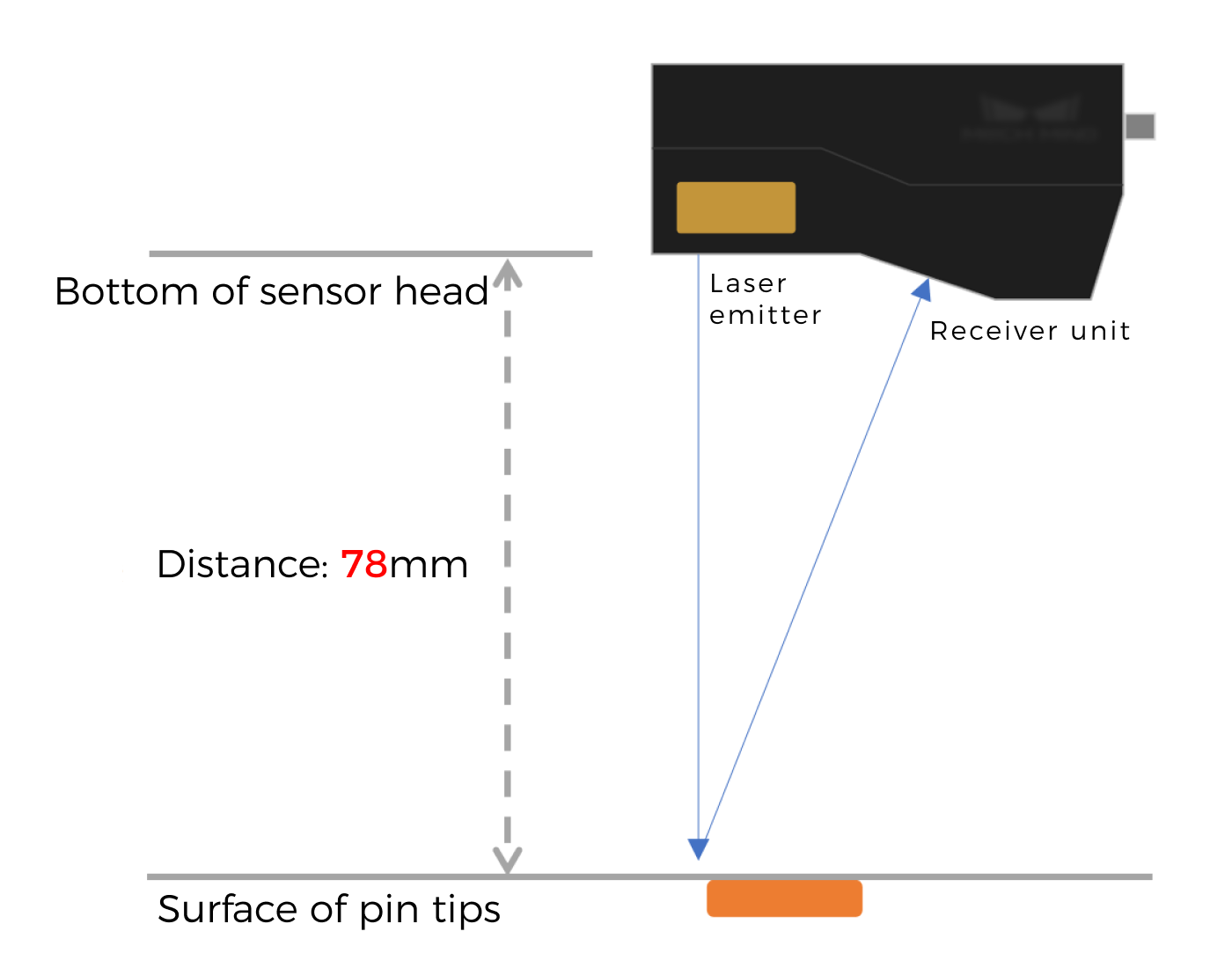
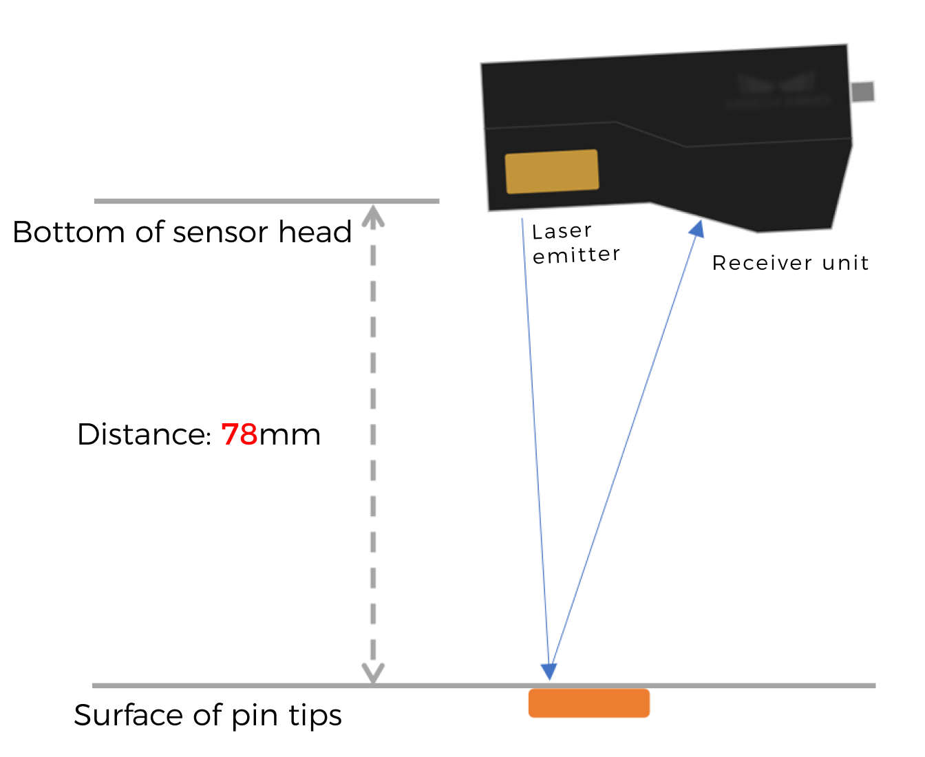
Vertical
Tilted
-
-
Mounting method: Securely mount the sensor head with a bracket.
For more information on mounting, see Mounting and Connection.
-
Software Installation
The 3D measurement system mainly involves the following software products:
-
Mech-Eye Viewer software (included in Mech-Eye SDK)
-
Mech-MSR 3D measurement and inspection software
Please visit the Download Center to obtain the latest versions of the software.
| It is recommended to use Mech-MSR 2.1.1 with Mech-Eye Viewer of version 2.4.0 or above. |
Connect the Laser Profiler to Acquire Data
-
Connect to the laser profiler.
Open Mech-Eye Viewer, find the device to be connected, and click the Connect button.
-
Acquire and view data.
The laser profiler obtains data by scanning an object line by line. For every line scan, a profile can be obtained, and profiles of all lines can be combined to generate an intensity image and a depth map.
See Acquire and View Data to learn how to use Mech-Eye Viewer to acquire high-quality data.
- Tuning experience
-
-
Adjust the Exposure Time parameter to make sure gray values at pin tips all fall within the range of 200–255. Underexposure may result in point cloud loss at pin tips, while overexposure can lead to excessive flying points at pin tips.
-
For metal pins, the Exposure Time parameter can typically be set between 20 and 30 μs, thus effectively reducing issues with reflection interference or excessive flying points.
-
Perform multiple scans to ensure that the acquired image data is complete and free of prominent point cloud loss.
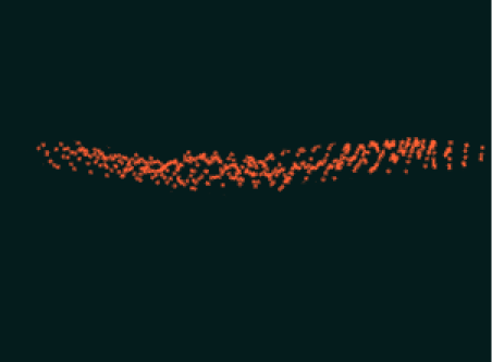
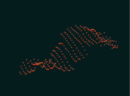
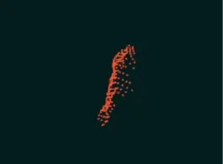
High-quality point cloud, very flat.
Average-quality point cloud, which can be processed by software.
Poor-quality point cloud, unusable.
-
-
Connect to the laser profiler in Mech-MSR.
Click the 3D Laser Profiler Step and disable Virtual Mode in the parameter configuration panel. Then, click the Select camera button to connect to the laser profiler and select the calibration parameter group.
-
Obtain image data.
In the graphical programming workspace of Mech-MSR, click the single-run icon
 on the right side of 3D Laser Profiler Step to run the Step and trigger data acquisition. In this way, the image data can be obtained.
Next, you can continue processing image data in the Mech-MSR software.