Fit Line to Surface Edge
Basic Concepts
Search Direction, Profile, and Edge Points
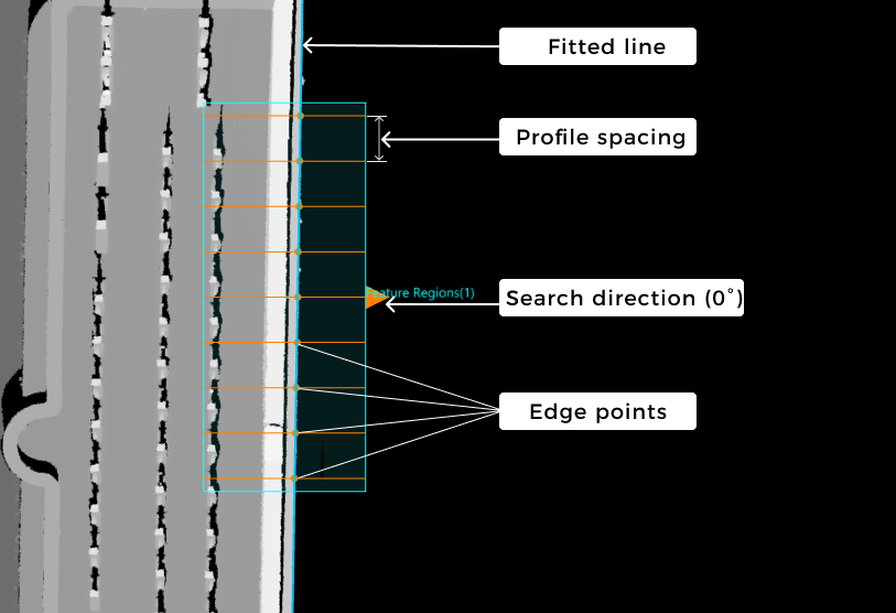
Set a feature region on the surface data, ensuring that it contains the straight edge to be detected. The depth or intensity value of data points at the edge will change significantly. To find out the points of significant changes, you can use the Step to extract evenly spaced profiles along the search direction. Each profile can well reflect the depth and intensity change of points at the edge. The search direction should be as perpendicular to the edge as possible. Then, you can detect edge points from the extracted profiles and use these points to fit a line.
|
As shown in the figure above, extracts evenly spaced profiles along the search direction (0°, the positive X-axis direction) and detects edge points from these profiles. |
In summary, the basic concepts you should grasp while using this Step are as follows:
-
Search direction
The direction along which the profiles are extracted in the feature region(s). The search direction should be as perpendicular to the edge as possible to better reflect changes in depth or intensity values of points at the edge.
-
Profiles and edge points
The Step will detect edge points that meet the requirements from each profile and fit a line with these points. An edge point is not necessarily a point on the profile. Instead, it is a point with the greatest gradient change calculated by the changes in depth and intensity.
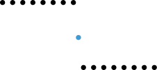
A profile, where the blue dot is the detected edge point.
Workflow
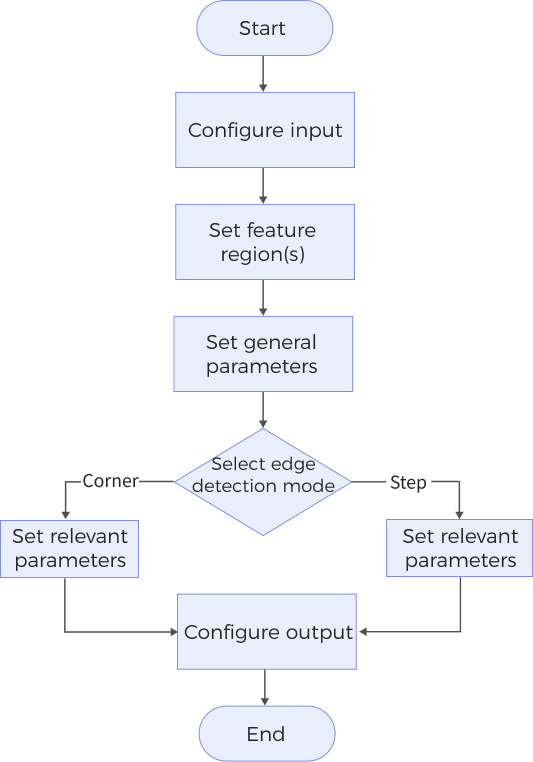
The process of configuring this Step is as follows:
-
Configure the input. Connect the Step ports in the graphical programming workspace or select the input under Input in the parameter configuration panel.
-
Set the feature region(s) for edge detection and line fitting.
-
Select the Edge Detection Mode and set the parameters accordingly.
-
Select the desired output items under Output. For an expandable output item, click ▶ and configure the Min and Max values to determine the acceptable range for the item.
Parameter Description
General Parameters
| Parameter | Description | ||
|---|---|---|---|
Use Intensity Image |
Select this option to use the intensity image for edge detection when the target detection region is flat, and the color differences in the region are prominent. Once selected, the Step uses the intensity image for straight edge detection and line fitting; otherwise, the Step uses the depth map by default. |
||
Feature Regions |
Set 1–4 feature region(s) for edge detection and line fitting. See Feature Regions to learn about how to adjust a feature region. |
||
Search Direction |
The direction for detecting edge points. The Step will extract profiles along the search direction to detect edge points. The search direction is defined as the angle of rotation about the Z-axis counterclockwise, relative to the positive X-axis direction. Value list: 0°, 90°, 180°, 270°
|
||
Fixed Angle |
Select this option to fix the angle of the fitted line when the actual edge angle is known. Once this option is selected, you should set Fixed Angle Value.
|
||
Fixed Angle Value |
The angle of rotation about the Z-axis counterclockwise, relative to the positive X-axis direction. The angle should be within -180°–180° Only visible when Fixed Angle is selected. |
||
Outlier Fraction |
The percentage of outlier points to be removed during line fitting. |
||
Edge Detection Mode |
The depth or intensity changing mode of data points at the edge.
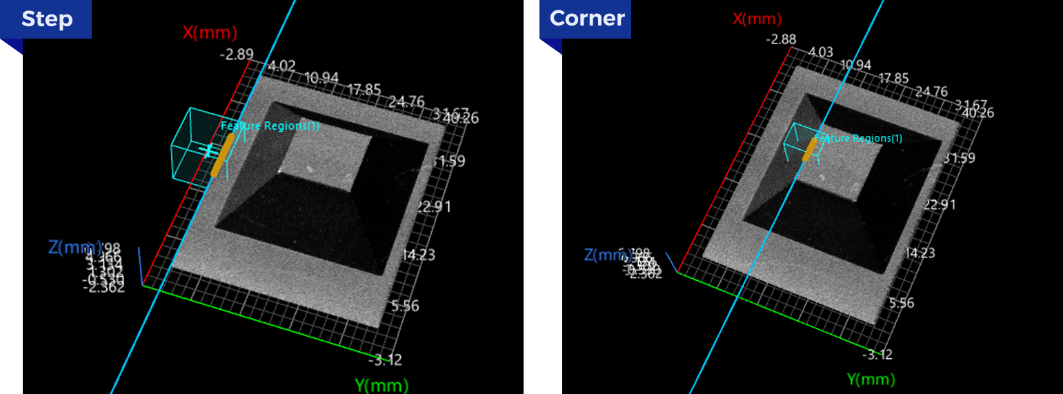
As shown in the figure, step edges exhibit a significant difference in data on both sides, often appearing as a sudden “drop” at the edge in the cross-section. In contrast, corner edges typically occur on sloped surfaces, where the data changes continuously on both sides, forming a corner at the edge in the cross-section. |
||
Fitted Line Direction |
Select an appropriate option from the drop-down list to determine the direction vector of the fitted line, thus determining the direction of the fitted line.
|
||
Profile Spacing |
The distance between adjacent profiles in the feature region(s). If the set spacing is less than the pixel width of a pixel, the Step will take the pixel width as the profile spacing.
|
||
Profile Averaging Width |
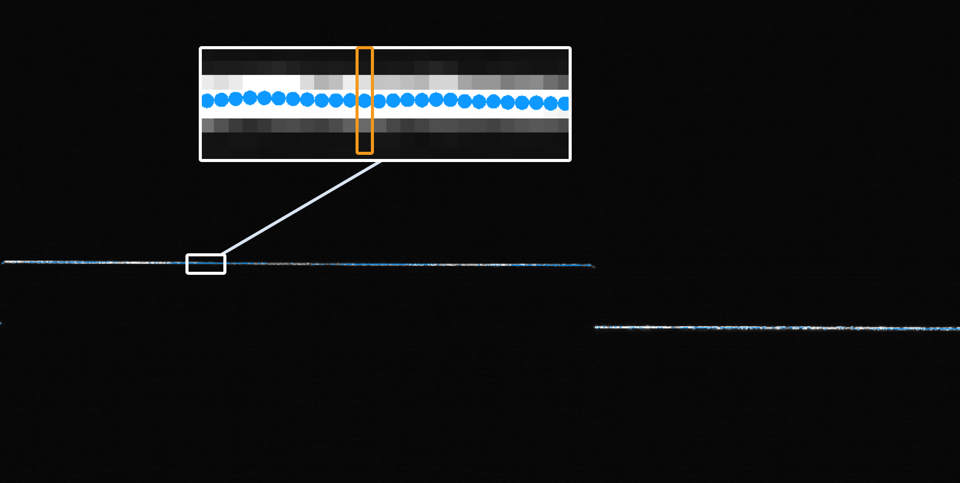
The size of the windows for calculating the average of data points along the direction perpendicular to the profile to obtain a smoother profile and thus reduce the impact of noise. When it is set to 0, no averaging operation will be performed on the profiles.
|
||
Show Detail |
Select this parameter to display the search direction in the visualization window. |
Step Edge Parameters
Set the parameters below when you set the edge detection mode to Step.
| Parameter | Description | ||
|---|---|---|---|
Window Size for Profile Smoothing |
The window size for filtering profiles along the search direction (the direction of profiles). After filtering, the profiles will be smoother. When it is set to 0, no filtering will be performed on the profiles along the search direction. 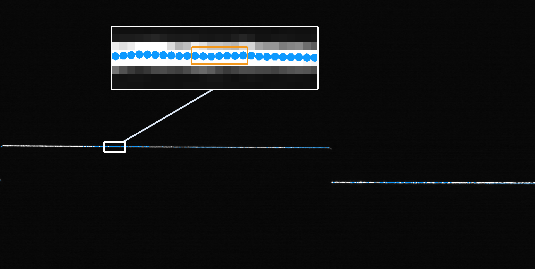
|
||
Gap Filling Threshold |
The data points on a profile may be subject to a gap due to occlusion. When the size of a gap on a profile is less than or equal to the set threshold, the nearest valid point from the lower side of the gap is used to fill it. When the gap size exceeds the set threshold, it remains as null point(s). 
|
||
Include Null Points |
Use this parameter to determine whether to include null points or not in the edge detection process. (Null points are points without depth or intensity information, which are often the result of data loss or inappropriate settings of the feature region(s).) Once this parameter is selected, set Null Filling Value of Depth.
|
||
Null Filling Value of Depth |
A depth value for filling null points. Only needs to be set after Include Null Points is selected. |
||
Null Filling Value of Intensity |
An intensity value for filling null points. Only needs to be set after both Use Intensity Image and Include Null Points are selected. |
||
Step Width |
The width of the step on a profile. When the step on a profile is a slope, set this parameter can help you accurately measure the step height and locate the position of the edge.
|
||
Step Direction |
The step direction along the search direction. Value list: Rising, Falling, Rising or falling. |
||
Step Type |
Set the type of step that will be selected from each profile. Value list: Best, First, Last. |
||
Absolute Threshold |
The minimum height variation for a potential step on a profile. When the parameter Use Intensity Image is selected, absolute threshold means the minimum intensity variation for a potential step on a profile. |
||
Use Relative Threshold |
Use this parameter to determine that a step is valid if the height (or intensity) change of the step is not less than the set percentage of the maximum change found on a profile. Once this parameter is selected, set Relative Threshold.
|
||
Relative Threshold |
Only visible when Use Relative Threshold is selected. |
Corner Edge Parameters
Set the parameters below when you set the edge detection mode to Corner.
| Parameter | Description | ||
|---|---|---|---|
Corner Type |
Select a proper corner type from the drop-down list to determine the edge point. Value list: First, Last, Top, Bottom, Best. |
||
Epsilon |
This parameter reflects the sensibility to the change of the profile shape. A larger value means that fewer points can meet the requirements, and thus it is more challenging to detect corners.
|
Output Description
Select the output item(s) to add the output port(s) to the Step, and the corresponding data will be output after the Step is run. You can select the output according to the actual measurement requirements.
|
If you select an expandable output item, you should expand it by clicking ▶, and then set the Min and Max values to determine the acceptable range. If the output value falls within the acceptable range, the measurement item is judged as passing (OK), or else it is judged as failing (NG). |
| Output item | Description | ||
|---|---|---|---|
Midpoint X |
The X value of the midpoint of the fitted line. |
||
Midpoint Y |
The Y value of the midpoint of the fitted line. |
||
Midpoint Z |
The Z value of the midpoint of the fitted line. |
||
Rotation Angle |
The rotation angle of the fitted line, i.e., the angle of rotation about the Z-axis counterclockwise, relative to the positive X-axis direction. If you have set a Fixed Angle Value, then the rotation angle is determined by both the fixed angle value and the fitted line direction. |
||
Average Step Size |
The average step height or intensity of all profiles. |
||
Edge Point Count |
The number of edge points used for line fitting. |
||
Min Error |
The error value of the edge point farthest below the fitted line, which is a negative number. |
||
Max Error |
The error value of the edge point farthest above the fitted line, which is a positive number. |
||
Fitted Edge Line |
The fitted line by detected edge points.
|
||
Center Point |
The intersection point of the fitted line with the line representing the search direction through the center point of Region1. |
||
Edge Plane |
The plane through the fitted line and parallel to the Z-axis. |
Troubleshooting
|
CV-W3301
Error: The “Profile Spacing” value is not within the valid range.
Possible cause: The parameter value is less than 0 or greater than the length of the longest side of the image.
Solution: Ensure the parameter value is greater than or equal to 0 and less than the length of the longest side of the image.
CV-W3302
Error: The “Window Size for Profile Smoothing” value is not within the valid range.
Possible cause:
-
The parameter value is less than 0 or greater than the length of the longest side of the image.
-
The parameter value is not within the valid range of the feature region(s).
Solution:
-
Ensure the parameter value is greater than or equal to 0 and less than the length of the longest side of the image.
-
Lower the parameter value or expand the feature region(s) to make sure the value is within the valid range.
CV-W3303
Error: The “Step Width” value is not within the valid range.
Possible cause:
-
The parameter value is less than 0 or greater than the length of the longest side of the image.
-
The parameter value is not within the valid range of the feature region(s).
Solution:
-
Ensure the parameter value is greater than or equal to 0 and less than the length of the longest side of the image.
-
Lower the parameter value or expand the feature region(s) to make sure the value is within the valid range.
CV-W3304
Error: The “Gap Filling Threshold” value is not within the valid range.
Possible cause: The parameter value is less than 0 or greater than the length of the longest side of the image.
Solution: Ensure the parameter value is greater than or equal to 0 and less than the length of the longest side of the image.
CV-W3305
Error: The “Outlier Fraction” value is not within the valid range.
Possible cause: The parameter value is less than 0 or greater than 100%.
Solution: Make sure the parameter value is within 0–100%.
CV-W3306
No edge points detected.
Possible cause:
-
The feature region is not set properly.
-
“Absolute Threshold” and “Relative Threshold” are too large.
-
The “Search Direction” is not set properly.
Solution:
-
Adjust the feature region to ensure edge points can be detected from the region(s).
-
Lower “Absolute Threshold” and “Relative Threshold” values.
-
The “Search Direction” should be as perpendicular to the edge to be detected as possible.
CV-W3307
The set Epsilon value is invalid.
Possible cause: The parameter value is less than 0.
Solution: Make sure the parameter value is greater than or equal to 0.
CV-W3308
Error: The “Profile Averaging Width” value is outside of the valid range.
Possible cause:
-
The parameter value is less than 0 or greater than the length of the longest side of the image.
-
The parameter value is not within the valid range the feature region(s).
Solution:
-
Ensure the parameter value is greater than or equal to 0 and less than the length of the longest side of the image.
-
Lower the parameter value or expand the feature region(s) to make sure the value is within the valid range.
CV-W3309
Error: The feature region settings are invalid.
Possible cause:
-
The length or width of the feature region(s) is less than or equal to 0.
-
The length or width of the feature region(s) is more than twice the length of the longest side of the image.
Solution:
-
Ensure that the length and width of the feature region(s) are greater than 0.
-
Ensure the length and width of the feature region(s) are less than twice the length of the longest side of the image.
CV-W3310
Error: The “Null Filling Value of Intensity” is outside of the valid range.
Possible cause: The parameter value is less than 0 or greater than 255.
Solution: Make sure the parameter value is within 0–255.
CV-W3311
Error: The “Null Filling Value of Depth” is outside of the valid range.
Possible cause: The parameter value is less than −10000 or greater than 10000.
Solution: Make sure the parameter value is within −10000–10000.
CV-W3312
Error: The set “Corner Type” is invalid.
Solution: Select a valid corner type from the drop-down list.
CV-W3313
Error: The “Relative Threshold” value is outside of the valid range.
Possible cause: The parameter value is less than 0 or greater than 1.
Solution: Make sure the parameter value is within 0–1.
CV-W3314
Error: The “Absolute Threshold” value is outside of the valid range.
Possible cause: The parameter value is less than 0 or greater than or equal to 255.
Solution: When the “Use Intensity Image” parameter is selected, ensure the absolute threshold is within 0–255.
CV-W3315
Error: The “Absolute Threshold” value is outside of the valid range.
Possible cause: The parameter value is less than 0 or greater than or equal to 10000.
Solution: Make sure the parameter value is within 0–10000.
CV-W3316
Error: The set “Edge Detection Mode” is invalid.
Solution: Select a valid edge detection mode from the drop-down list.
CV-W3317
Error: The set “Search Direction” is invalid.
Solution: Select a valid search direction from the drop-down list.
