Measure Cylinder
Description
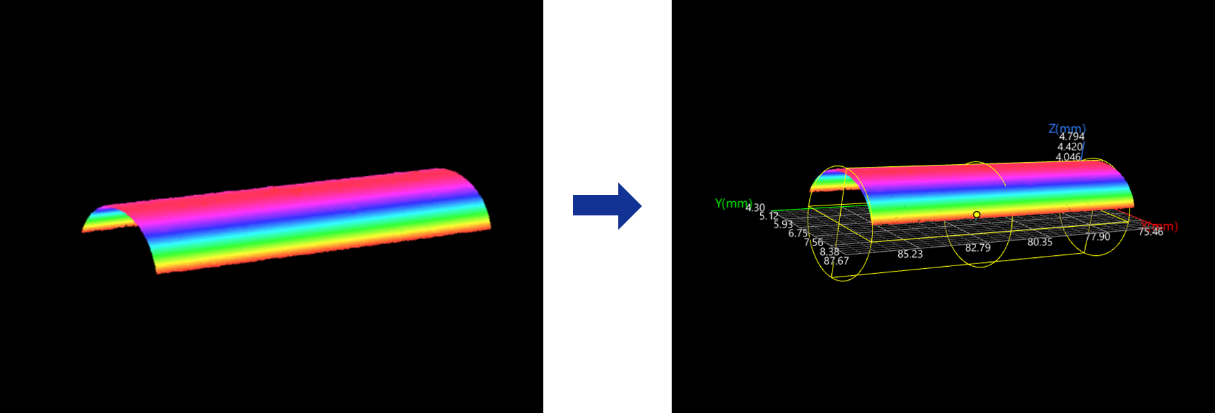
This Step is used to fit a cylinder from the surface data and calculate the cylinder’s radius, center point, tilt angle, etc.
Workflow
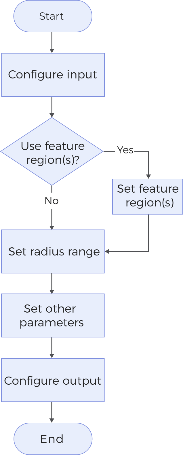
The process of configuring this Step is shown below:
-
Configure the input. Connect the Step ports in the graphical programming workspace or select the input under Input in the parameter configuration panel.
-
Determine whether to use a feature region.
-
Set the step size for downsampling.
-
Set other parameters.
-
Select the desired output items under Output. For an expandable output item, click ▶ and configure the Lower Limit and Upper Limit values to set the acceptable range.
Parameters
| Parameter | Description |
|---|---|
Use Feature Region |
When unselected, the Step processes all of the surface data to fit the cylinder. Otherwise, the Step only processes the surface data defined by the feature region(s).
|
Downsampling Step |
This Step is used to downsample surface data before fitting a cylinder. The larger the value, the fewer data points involved in the calculation, and the processing speed is usually faster. Value range: 1 to 16. “1” indicates no downsampling. If the fitting speed is slow, increase the Step size appropriately to improve the processing speed. |
Output Description
Select the output item(s) to add the output port(s) to the Step, and the corresponding data will be output after the Step is run. You can select the output according to the actual measurement requirements.
|
If you select an expandable output item, you should expand it by clicking ▶, and then set the Lower Limit and Upper Limit values to determine the acceptable range. If the output value falls within the acceptable range, the measurement item is judged as passing (OK), or else it is judged as failing (NG). |
| Output Item | Description |
|---|---|
Radius |
The radius of the fitted cylinder. |
Center X/Y/Z |
The location of the fitted cylinder’s center. |
Axis-Z Angle |
The angle between the axis of the fitted cylinder and the positive Z-axis. |
Axis-X Angle |
The angle between the axis of the fitted cylinder and the positive X-axis. |
X/Y/Z-Component of Axis Vector |
The x-, y-, and z-components of the axis vector of the fitted cylinder, respectively. |
Center of Cylinder |
The midpoint of the line connecting the centers of the upper and lower bases of the fitted cylinder. The output is a point with coordinate information. |
Axis of Cylinder |
The axis of the fitted cylinder, passing through the centers of its upper and lower bases. The output is a line with direction information. |
Cylinder |
Fit the obtained cylinder. |
Troubleshooting
|