Communication and I/O Control
This chapter describes interaction methods among external devices (such as PLCs), Mech-MSR, and laser profilers or cameras in 3D measurement and inspection applications.
Overview
External devices (such as PLCs) can interact with Mech-MSR in the following ways:
-
Protocol-based communication
This refers to interaction between external devices and Mech-MSR based on standard or custom industrial communication protocols.
Mech-MSR supports multiple communication protocols, such as TCP ASCII, PROFINET, Mitsubishi MELSEC (MC), EtherNet/IP, Modbus TCP, and Siemens S7. For more information, see Protocol-based Communication.
-
I/O control
This refers to interaction between external devices and Mech-MSR through the general digital input/output (DI/DO) terminals on a laser profiler. It is suitable for production scenarios that require fast response or fixed takt timing. For more information, see I/O Control.
Typical Interaction Methods (Laser Profiler Scenarios)
In laser profiler scenarios, Mech-MSR needs to obtain data (surface data or point clouds) from the profiler. The signals that trigger the profiler to acquire data can be divided into two types:
-
Software trigger (sent by Mech-MSR)
-
External trigger (sent by an external device, such as a PLC or photoelectric sensor)
By combining the trigger method for running a Mech-MSR project and the trigger method for laser profiler data acquisition, 3D measurement and inspection applications support the following typical interaction methods:
| Method | Method for triggering Mech-MSR project execution | Trigger source for laser profiler data acquisition | Method for external devices to obtain results |
|---|---|---|---|
Communication command |
Software trigger |
Communication command |
|
Run upon image update |
External trigger |
TCP ASCII protocol or DO signal |
|
DI signal |
External trigger |
TCP ASCII protocol or DO signal |
|
Communication command |
External trigger |
Communication command |
|
DI signal |
Software trigger |
DO signal |
Method 1: Protocol Communication + Software Trigger
In this method, communication between external devices and Mech-MSR is protocol-based, and the laser profiler is triggered by Mech-MSR to acquire data.
Advantages |
You can conveniently switch laser profiler parameter groups in Mech-MSR. |
|---|---|
Disadvantages |
Both communication trigger and software trigger introduce latency, and the delay is unstable. Because the trigger chain contains multiple non-real-time links, overall timing is difficult to control precisely. Therefore, this method is not suitable for scenarios that require synchronization with a motion platform or fixed-frequency acquisition. |
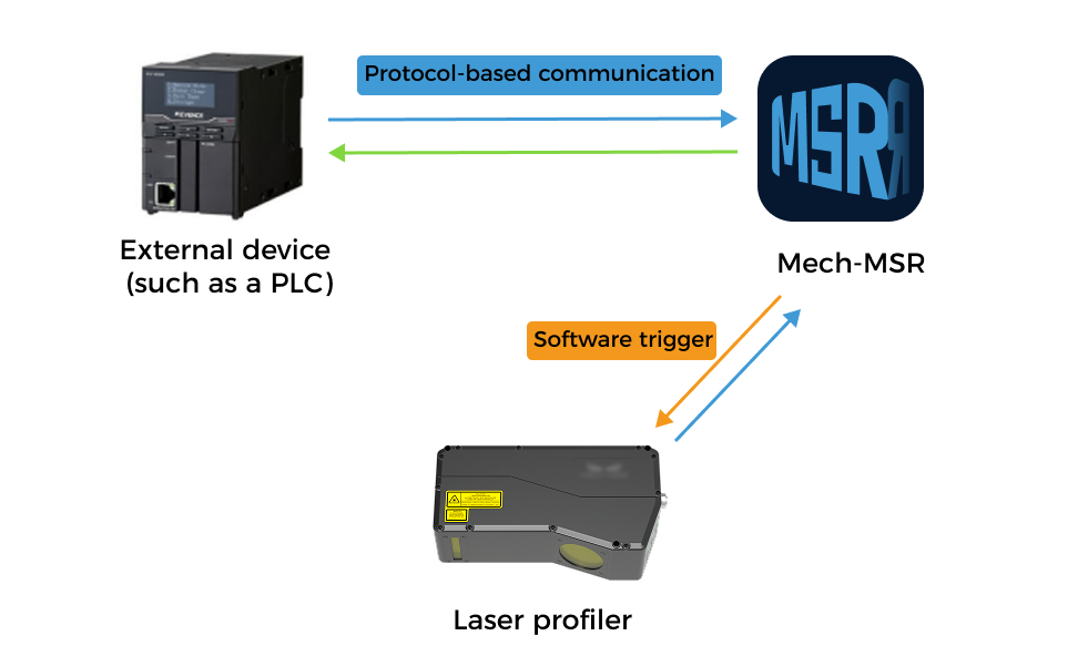
The interaction flow among external devices, Mech-MSR, and the laser profiler is as follows:
-
An external device sends a command to trigger a Mech-MSR project.
-
The Mech-MSR project starts and triggers the laser profiler to acquire data.
-
After Mech-MSR receives the data acquired by the profiler, it continues running the project until completion.
-
Mech-MSR returns corresponding results to the external device based on received commands.
Method 2: Run Upon Image Update + External Trigger
In this method, an external device triggers the laser profiler to acquire data. After receiving the acquired data, Mech-MSR runs the project (that is, Run upon image update is enabled), and sends project results to the external device through the TCP ASCII protocol or DO signals.
Advantages |
External triggering has no delay and provides fast response. |
|---|---|
Disadvantages |
Laser profiler parameter groups cannot be switched. Therefore, this method is not suitable for scenarios where multiple Mech-MSR projects use the same laser profiler and require different parameter groups. |
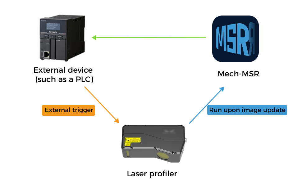
The interaction flow among external devices, Mech-MSR, and the laser profiler is as follows:
-
An external device triggers the laser profiler to acquire data.
-
In Mech-MSR, projects that use this profiler enable Run upon image update. After receiving data from the profiler, the project starts automatically.
-
Mech-MSR sends project results to the external device based on the configuration.
External devices can obtain project results in two ways:
-
Through the Auto Push Result function supported by the TCP ASCII protocol to promptly obtain all results.
-
Through the general DO terminals on the laser profiler based on DO configuration in Mech-MSR, to obtain the overall quality judgment result (OK or NG) of the Mech-MSR project.
-
Method 3: DI Trigger + External Trigger
In this method, an external device triggers the laser profiler to acquire data, triggers Mech-MSR project execution through general DI terminals, and obtains project results through the TCP ASCII protocol or DO signals.
Advantages |
External triggering has no delay and provides fast response. |
|---|---|
Disadvantages |
Laser profiler parameter groups cannot be switched. Therefore, this method is not suitable for scenarios where multiple Mech-MSR projects use the same laser profiler and require different parameter groups. |
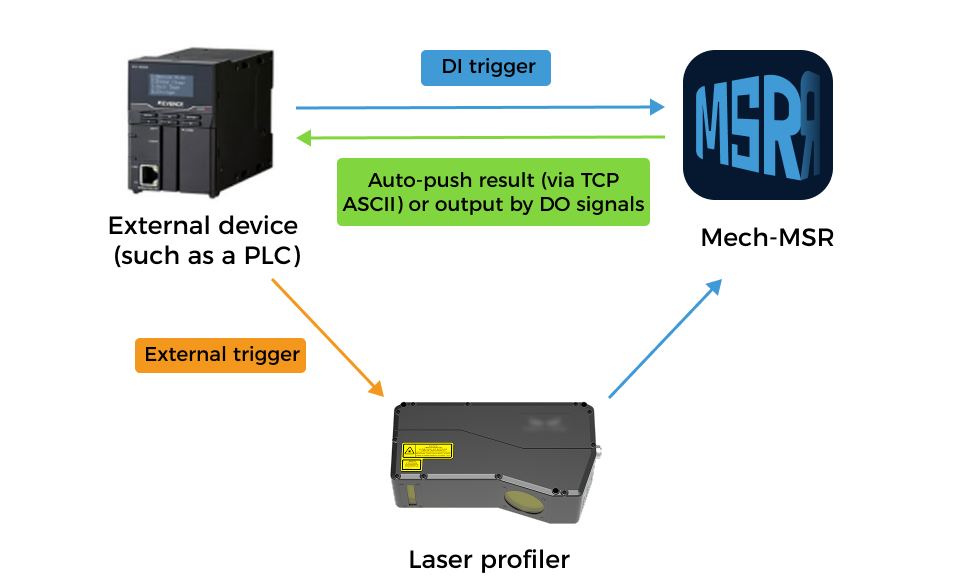
The interaction flow among external devices, Mech-MSR, and the laser profiler is as follows:
-
An external device triggers the laser profiler to acquire data.
-
Based on DI configuration in Mech-MSR, the external device triggers the corresponding Mech-MSR project through the general DI terminals on the profiler.
-
Mech-MSR sends project results to the external device based on the configuration.
External devices can obtain project results in two ways:
-
Through the Auto Push Result function supported by the TCP ASCII protocol to promptly obtain all results.
-
Through the general DO terminals on the laser profiler based on DO configuration in Mech-MSR, to obtain the overall quality judgment result (OK or NG) of the Mech-MSR project.
-
Method 4: Protocol Communication + External Trigger
In this method, an external device triggers the laser profiler to acquire data while communicating with Mech-MSR through a protocol.
Advantages |
External triggering has no delay and provides fast response. |
|---|---|
Disadvantages |
Laser profiler parameter groups cannot be switched. Therefore, this method is not suitable for scenarios where multiple Mech-MSR projects use the same laser profiler and require different parameter groups. |
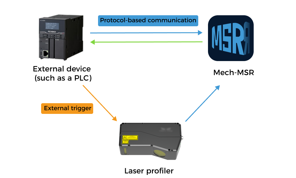
The interaction flow among external devices, Mech-MSR, and the laser profiler is as follows:
-
An external device triggers the laser profiler to acquire data.
-
The external device sends a command to trigger a Mech-MSR project.
-
Mech-MSR returns corresponding results to the external device based on received commands.
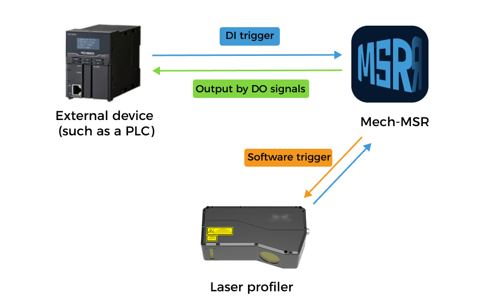
Method 5: DI Trigger + Software Trigger
In this method, an external device triggers Mech-MSR project execution through the general DI terminals on the laser profiler, and obtains project results through DO signals. The laser profiler is triggered by Mech-MSR for data acquisition.
Advantages |
Pure hardware connection, no programming required. |
|---|---|
Disadvantages |
External devices can only obtain the overall quality judgment result (OK or NG) of the project, but cannot obtain measurement values or their judgment results. |
The interaction flow among external devices, Mech-MSR, and the laser profiler is as follows:
-
Based on DI configuration in Mech-MSR, an external device triggers the corresponding Mech-MSR project through the general DI terminals on the laser profiler.
-
The Mech-MSR project starts and triggers the laser profiler to acquire data.
-
Based on DO configuration in Mech-MSR, the external device obtains the overall quality judgment result of the Mech-MSR project through the general DO terminals on the profiler.
Typical Interaction Method (2D/3D Camera Scenarios)
In 3D measurement and inspection applications using 2D/3D cameras, the interaction flow among external devices, Mech-MSR, and the camera is as follows:
-
An external device sends a command to trigger a Mech-MSR project.
-
The Mech-MSR project starts and triggers the camera to capture images.
-
After Mech-MSR receives images captured by the camera, it continues running the project until completion.
-
Mech-MSR returns corresponding results to the external device based on received commands.