Understand Control Flow in Mech-MSR Projects
What Is Control Flow?
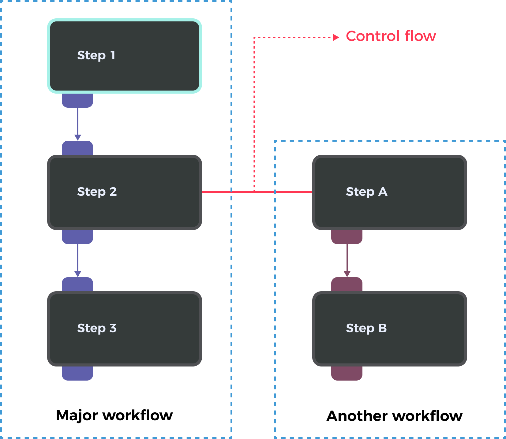
In a Mech-MSR project, Steps are connected from top to bottom, and during execution, data flows sequentially from the first Step to the last, forming a complete vision processing workflow. In most cases, a project contains only one workflow. However, the software also supports configuring multiple workflows within a single project. One workflow can trigger the execution of another via control flow.
For example, in the figure below, when Step 2 is executed, it triggers the control flow to run Workflow A→B.
| If a project contains multiple workflows, control flow must be configured; otherwise, the project cannot run. |
How to Configure Control Flow?
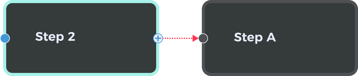
In the graphical programming workspace of the home interface, when a Step is selected, you will see connection points on both sides of the Step card. These are used to define control flows. The right-side point of the Step card is the starting point of the control flow. The left-side point of another Step card is the receiving point. Connect the points as needed to form a control flow.
|
Configuring control flows between Steps in the same workflow is allowed, but this operation will disable the sub-workflow starting from the Step receiving the control flow. In this case, any control flow-related parameters under Execution Flags will become invalid. 
|
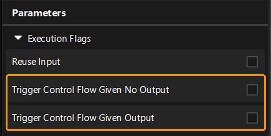
Trigger Control Flow Given Output / Given No Output
When running a project, you can configure relevant settings to trigger other workflows to run, regardless of whether the Step that initiates the control flow produces any output.
In the graphical programming workspace of the home interface, select the Step and expand Execution Flags in the parameter configuration panel. There, you can choose either Trigger Control Flow Given No Output or Trigger Control Flow Given Output to define the desired behavior.