Alignment Parameter Group
This section introduces how to use the “Alignment Parameter Group.”
Usage Scenario
It is hard to ensure the target object is in the same position in every acquired image. You may encounter the following:
-
Object translation: The target object moves along the X-, Y-, or Z-axis.
-
Object rotation: The target object rotates about the Z-axis.
To ensure the consistency of subsequent measurements, you can use the following two methods to cope with the above situations:
-
Align Input Data
To address misalignment in images or data, you can create a matching template by extracting typical features of the target object, and use the template to correct the object’s position. Regardless of how the object’s position changes, the object remains in the same position after alignment, ensuring the subsequent measurements will not be affected.
-
Transforming feature regions
In typical scenarios, feature regions do not automatically adjust with the position of the target object. If the object moves, you would need to adjust the feature regions manually, which is both repetitive and cumbersome. To make the feature region change with the target object’s position, information about the object’s translation and rotation can be extracted. Accordingly, the feature region can be rotated or translated to ensure it always covers the target area accurately, unaffected by the object’s position changes.
The data collection of the object’s position changes is the Alignment Parameter Group. Simply put, the Alignment Parameter Group ensures that when the target object’s position changes, the feature region adjusts accordingly, maintaining consistent measurements.
| In general, Alignment Parameter Group is only valid if a feature region or feature regions are used in a Step and serves to adjust their position. There is only one exception where the alignment parameter group can be used to adjust the position of the track line in the Measure Surface Track Step. |
How to Obtain the Alignment Parameter Group?
Currently, you can obtain the alignment parameter group by the following methods:
Use the “Extract Alignment Parameter Group” Step
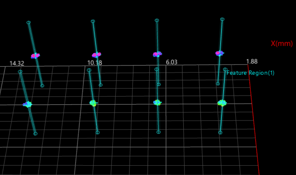
You can use the Extract Alignment Parameter Group Step to directly create an Alignment Parameter Group.
| The purpose of extracting the alignment parameter group is to ensure that the set feature region(s) can be automatically adjusted as the object’s position changes. Therefore, when creating an alignment parameter group, you should make sure that the parameters used are capable of accurately transforming the position of feature regions. |
- Example
-
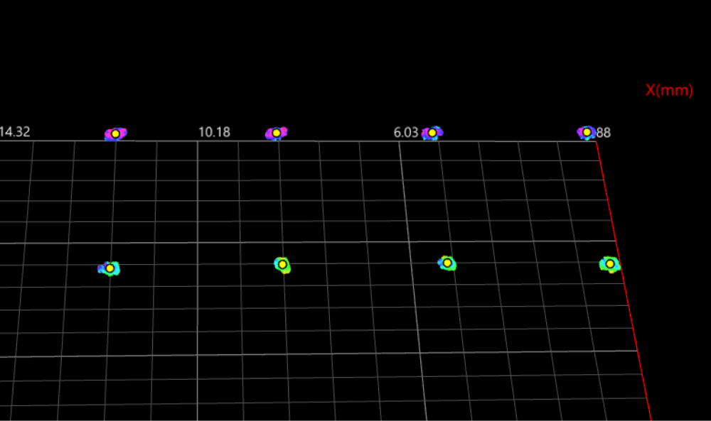
After extracting the surface data of pin tips, you can create an Alignment Parameter Group on the basis of the center points of each pin tip to further narrow down the data range. Then, when using the Process Surface by Filter Step to crop the extracted surface data, set a feature region for the surface data of one pin tip to establish the correspondence between the feature region and the center point. The feature regions for other pin tips will then be automatically adjusted accordingly.
When the position of pins changes, the feature regions can be automatically adjusted according to the correspondence established during the initial tuning process if the center points of pin tips are determined.
① Extract surface data of pin tips
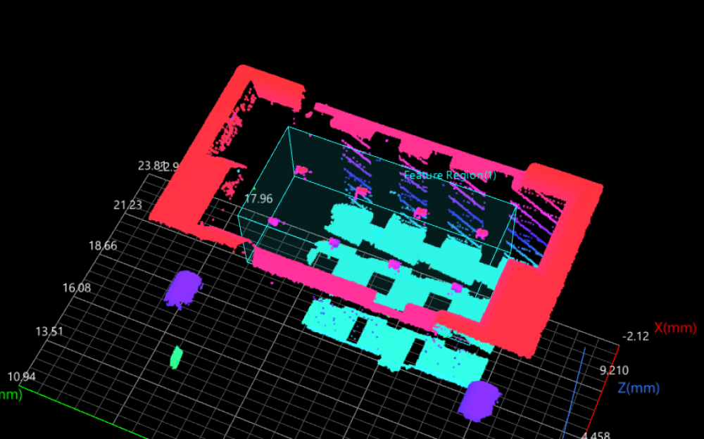
② Obtain center points of pin tip data
③ Create an alignment parameter group
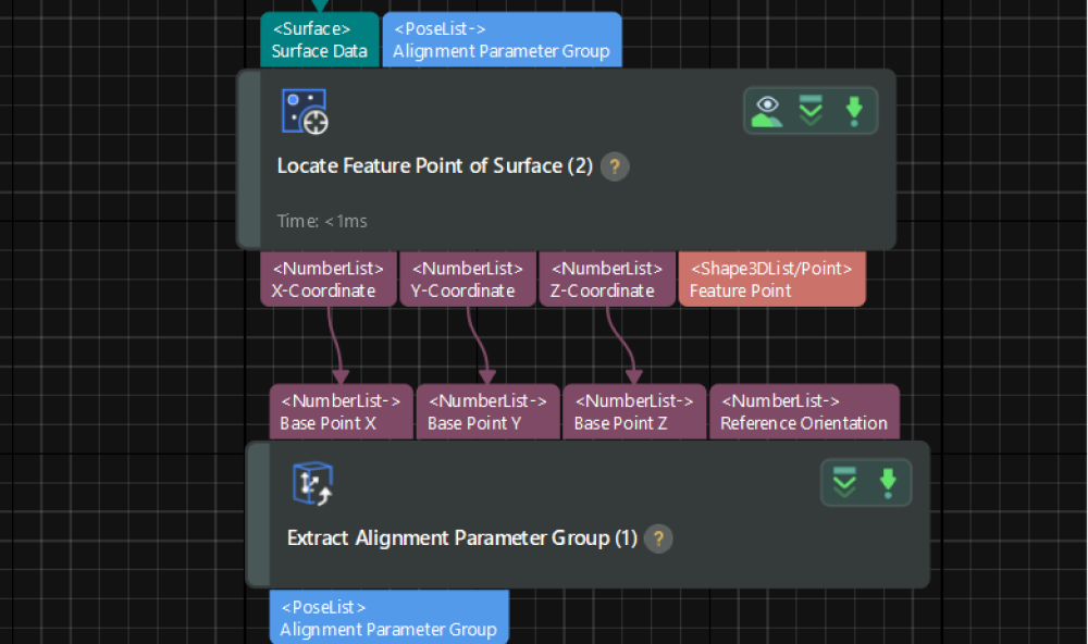
④ Adjust a feature region
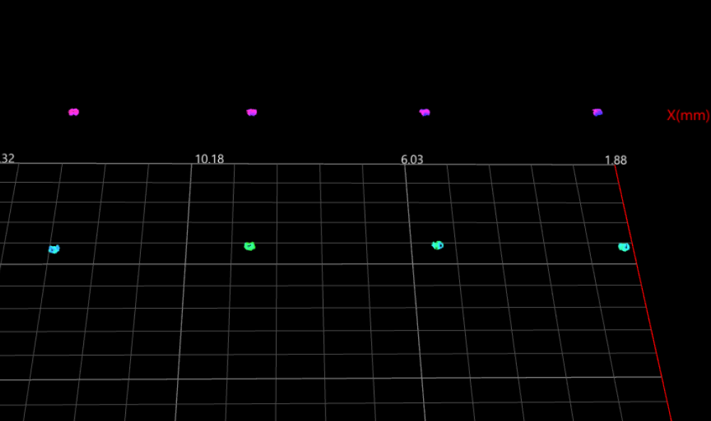
⑤ Narrow down the data range
Use the “Alignment/Matching” Step
The following Steps can all calculate the translation and rotation of a target object based on a created matching template, and output an alignment parameter group:
| Step | Data Type | Output |
|---|---|---|
Surface data |
Aligned surface data and alignment parameter group. |
|
Surface data |
Matching results and alignment parameter group. |
|
2D image |
Aligned image and alignment parameter group. |
|
2D image |
Matching results and alignment parameter group. |
The alignment parameter group output by these Steps can be input into subsequent Steps that use feature regions, to rotate or translate the feature regions accordingly.
|
- Example
-
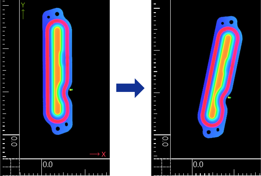
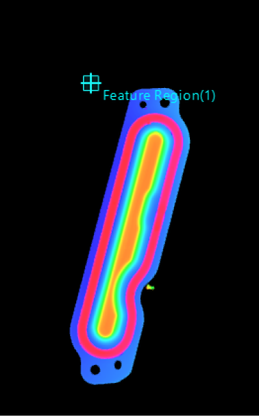
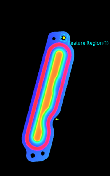
When the target object’s position changes in the image, the alignment parameter group enables the feature regions to change accordingly: (The following examples are based on 3D scenarios; the same principles apply to 2D scenarios.)
Change Illustration Alignment parameter group not used Alignment parameter group used Translation
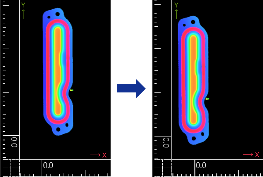
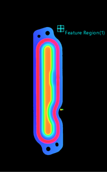
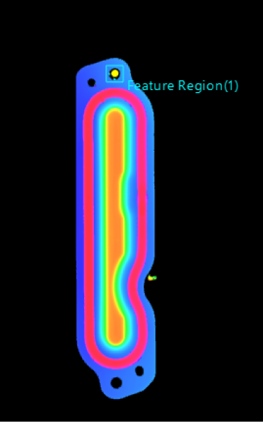
Rotation