Measure Dimensions by Surface Features
Description
This Step is used to locate two feature points on a surface and perform measurements on this basis, including width (X-axis), length (Y-axis), height (Z-axis), distance, and X / Y / Z values of the midpoint.
Workflow
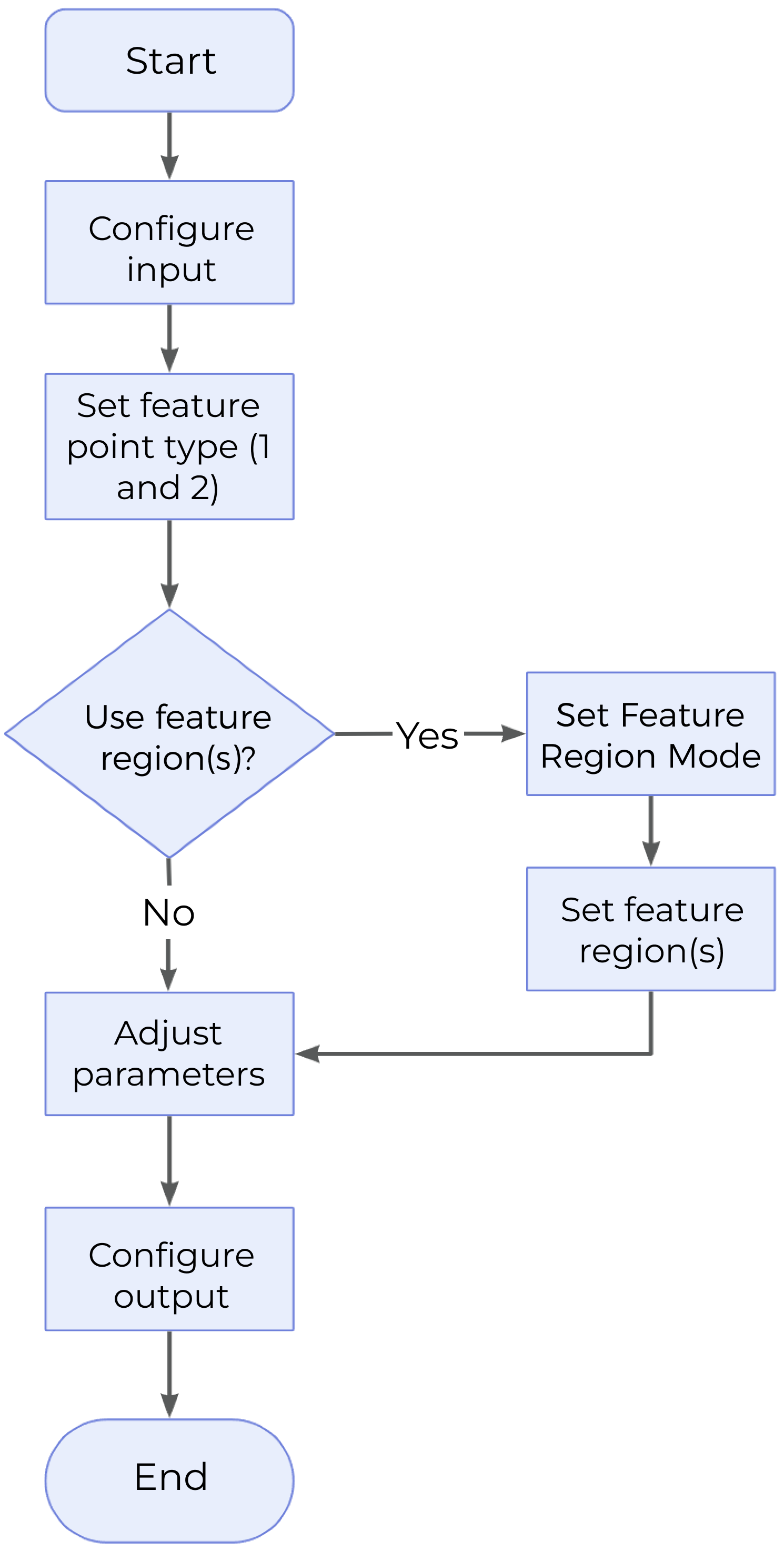
The process of configuring this Step is as follows:
-
Configure the input. Connect the ports manually or select the input(s) under Input in the parameter configuration panel.
-
Identify two feature points. Specify two feature point types under Type of Feature Point 1 and Type of Feature Point 2, respectively. Define the regions for the selected feature points by selecting Use Feature Region 1 and Use Feature Region 2 as well as completing the configuration.
-
Set other parameters according to the actual requirements.
-
Select the desired output items under Output. For an expandable output item, click ▶ and configure the Lower Limit and Upper Limit values to set the acceptable range.
Parameter Description
| Parameter | Description |
|---|---|
Type of Feature Point 1 / Type of Feature Point 2 |
Specify the type of the feature point from the drop-down menu. For more detailed information, please refer to Feature Points. |
Use Feature Region 1 / Use Feature Region 2 |
|
Output Absolute Width / Length / Height |
|
Output Description
Select the output item(s) to add the output port(s) to the Step, and the corresponding data will be output after the Step is run. You can select the output according to the actual measurement requirements.
|
If you select an expandable output item, you must expand it by clicking ▶, and then set the Lower Limit and Upper Limit values to determine the acceptable range. If the output value falls within the qualified range, the measurement is judged as passing (OK), or else it is judged as failing (NG). |
| Output Item | Description | Illustration |
|---|---|---|
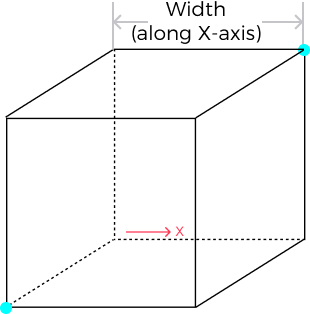
Width |
The distance between two feature points along the X-axis. |
|
Length |
The distance between two feature points along the Y-axis. |
|
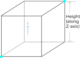
Height |
The distance between two feature points along the Z-axis. |
|
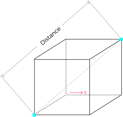
Distance |
The Euclidean distance between two points. |
|
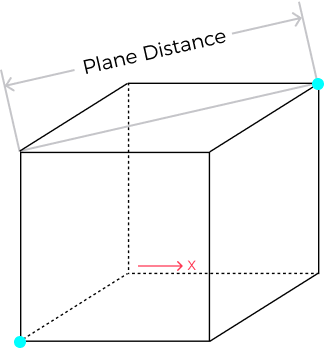
Plane Distance |
The point with the lower Z-value is projected onto the plane (perpendicular to the Z-axis) where the other point is located, and the distance on the plane is the plane distance. |
|
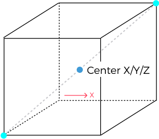
Midpoint X / Midpoint Y / Midpoint Z |
X, Y, and Z values of the midpoint between the two points, respectively. |
|

Troubleshooting
See Error Code List for common error messages and solutions.