3D Laser Profiler
Description
This Step, which is generally the first Step in a measurement project, is used to acquire the image data or point cloud data. With this Step, you can connect to Mech-Eye 3D Laser Profiler (hereinafter referred to as “laser profiler”) to acquire data, or read locally saved data in the virtual mode.
Workflow
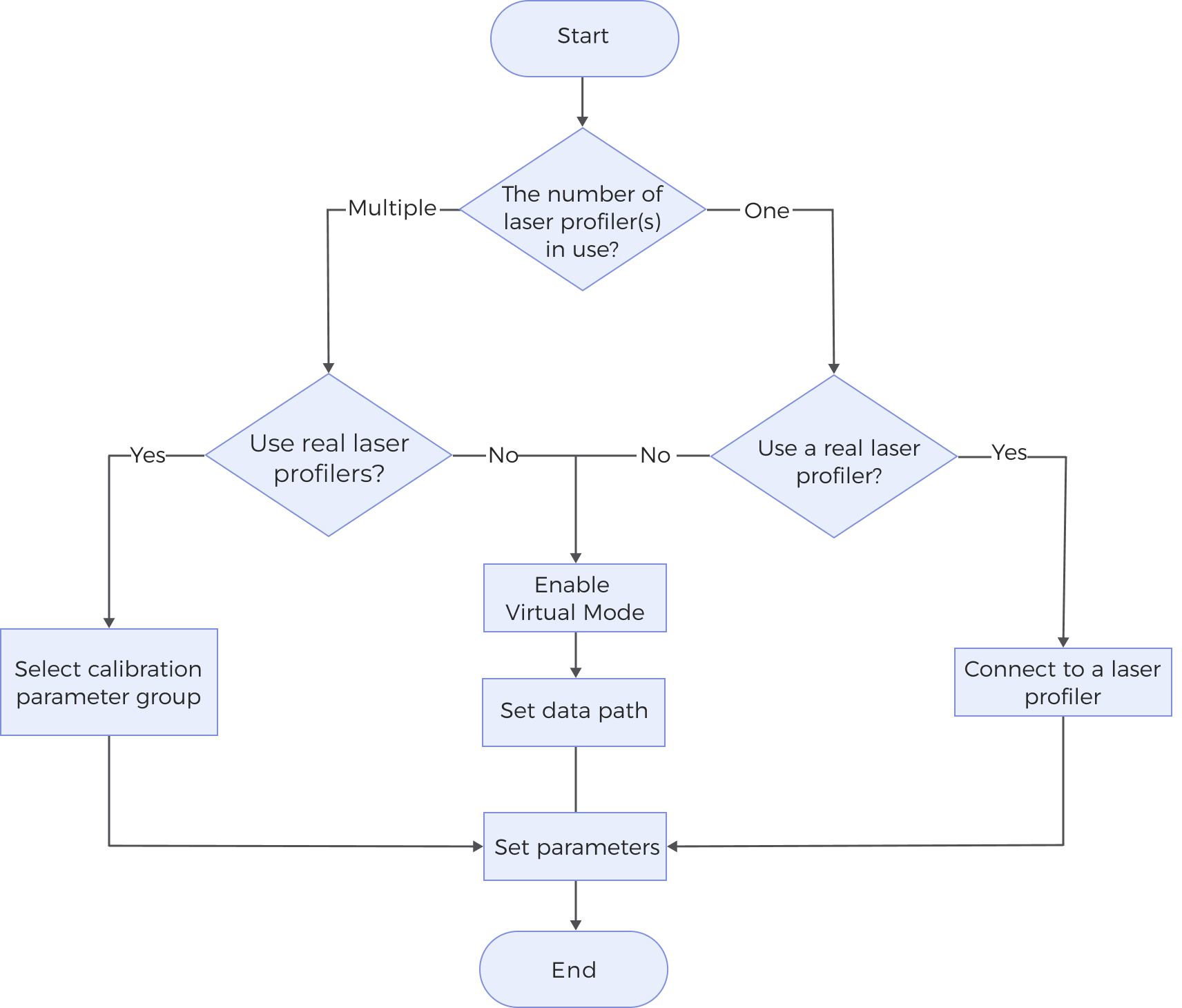
The process of configuring this Step is shown below:
-
Select the number of laser profilers in use.
-
Determine whether to Use Real Laser Profiler(s) or Load Locally Saved Data.
-
Set Parameters.
Use Real Laser Profiler(s)
Preparations
-
One laser profiler
-
Multiple laser profilers
-
Complete relevant settings in Mech-Eye Viewer:
-
Connect to the laser profiler in Mech-Eye Viewer.
-
Adjust parameters in Profile Mode and Scan Mode and save the parameter group.
-
| The version of Mech-Eye Viewer should be 2.3.4 or higher. |
-
Complete Multiple Laser Profiler Calibration.
-
Configure the parameter groups of laser profilers to be connected in Mech-Eye Viewer.
| The version of Mech-Eye Viewer should be 2.5.0 or higher. |
Workflow
-
One laser profiler
-
Multiple laser profilers
-
Drag the Step to the graphical programming workspace.
-
In the Parameters section of this Step, set Camera Mode to One.
-
Click the Select camera button to open the Choose the camera and calibration parameter group to use window.
In this context, camera refers to the laser profiler. -
Find the camera to connect in the Camera ID list, hover the cursor over the camera ID, and click
 to connect to the camera.
If becomes  , the camera is connected successfully.
-
After the camera is connected successfully, you can select the calibration parameter group in the drop-down list of Calibration Parameter Group and then click the OK button in the lower-right corner of the window. Some parameters will be automatically updated in the Parameters section.
-
If you need to apply calibration results of a single laser profiler, you can select Tilt Correction, S/Z Scan Stitching, or Apply N-Point Calibration according to the scenario, and then follow the interface prompts to select the corresponding calibration result and complete the related parameter settings.
-
If you need to apply the results of Tilt Calibration (Auto) or Tilt Calibration (Manual), select Tilt Correction.
-
If you need to apply the result of Stitching Calibration, select S/Z Scan Stitching, and click Open the editor under Scan Segment Settings to complete the scan segment configuration.
-
If you need to apply the result of N-Point Calibration, select Apply N-Point Calibration, and configure Acquisition Start Position X, Acquisition Start Position Y, and Acquisition Start Position Z.
-
Tilt Correction and S/Z Scan Stitching cannot be selected at the same time, which means these two types of calibration results cannot be applied simultaneously.
-
-
Set Parameters.
-
Run this Step to obtain image data.
-
Drag the Step to the graphical programming workspace.
-
Set the Camera Mode to Multiple.
-
Select the calibration result under the Calibration Result of Laser Profilers in the Parameters section.
-
The result of multiple laser profiler calibration is saved in the
calibrationfolder in the project directory. -
The model, IDs, and ROI settings of laser profilers should be consistent with those during calibration.
-
-
After the parameter group is selected, the information about the used devices will be automatically updated under Camera Info.
Ensure that grouped laser profilers have identical trigger settings (with the exception of trigger delay) and resolution settings. -
If you need to apply the result of Stitching Calibration, you can select S/Z Scan Stitching, choose the result of Stitching Calibration, and click Open the editor under Scan Segment Settings to complete the scan segment configuration.
-
Set Parameters.
-
Run this Step to obtain image data.
Load Local Data
Preparations
-
One laser profiler
-
Multiple laser profilers
Acquire and save data with a laser profiler. For related operations, refer to Acquire and View Data and Save Data instructions.
Ensure that local image data is available. Normally, when acquiring data by using real laser profilers, you can use Data Storage feature to store data to a local directory.
Workflow
-
One laser profiler
-
Multiple laser profilers
-
Drag the Step to the graphical programming workspace.
-
In the Parameters section of this Step, set Camera Mode to One and enable the Virtual Mode.
-
Click the icon
 under Data Path.
 -
In the pop-up window, browse and select the folder where the data is saved and then click the Select Folder button.
If the selected folder does not contain valid data of the virtual camera, a Virtual Camera Assistant window will pop up. You need to manually select the path to the folder that contains the MRAW files of the virtual camera. Note that you should use Mech-Eye Viewer (version 2.3.4 or later) to save the MRAW files of the virtual camera. 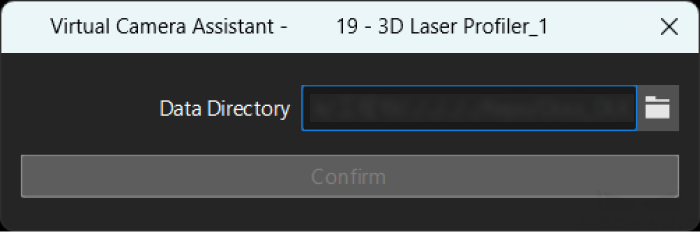
-
Set Parameters.
-
Run this Step to load the locally saved data.
-
Drag the Step to the graphical programming workspace.
-
In the Parameters section of this Step, set Camera Mode to Multiple and enable the Virtual Mode.
-
Click the icon
under Data Path. -
In the pop-up window, browse and select the folder where the data is saved and then click the Select Folder button, and the Calibration Parameter Group will be updated automatically.
-
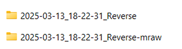
As shown in the figure below, the selected folder should contain at least a group of calibration data and image data (in MRAW format).
-
The folder names of the calibration data and MRAW-format image data are composed of the data storage date and time, the laser profiler layout, and a custom suffix. If you set a custom suffix, it must be identical in both folder names; otherwise, data loading will fail.
-
-
Set Parameters.
-
Run this Step to load locally saved data.
Parameters
Camera Mode
Parameter description: The parameter is used to select whether to use One or Multiple laser profilers for the current project.
Camera Type
Parameter description: This parameter is used to select the laser profiler type in use. Currently, only LNXCamera is supported, i.e., the Mech-Eye 3D Laser Profiler.
Basic Settings
Frequently Used Parameters
| Parameter | Description | ||
|---|---|---|---|
Virtual Mode |
Disabled by default. If you need to run the project with the locally saved data, you can enable the Virtual Mode. |
||
Camera ID |
Confirm the ID of the camera to be connected. Click the Select camera button and select the camera to connect. Refer to Workflow for detailed instructions. |
||
Camera IP |
IP address of the laser profiler.
|
||
Configuration Parameter Group |
The laser profiler acquires data according to the parameters in the parameter group configured in Mech-Eye Viewer. |
||
Update Configuration Parameter Group |
If you have modified and saved the selected configuration parameter group in Mech-Eye Viewer, you can click the Get updates button to update the parameter group.
|
||
Calibration Parameter Group |
The parameter group used by the selected laser profiler. |
||
Tilt Correction |
Only visible when one laser profiler is used for data acquisition. Select this option to apply the result of Tilt Calibration (Auto) or Tilt Calibration (Manual) to geometrically correct the acquired data. This is used to eliminate data distortion and measurement errors caused by the mounting tilt of the sensor head about the X, Y, and Z axes. Once this option is selected, you need to select the result of tilt calibration.
|
||
S/Z Scan Stitching |
If the laser profiler needs to scan the same target in the back-and-forth (S-shaped) or unidirectional (Z-shaped) manner to achieve segmented data acquisition and data stitching, select this option and apply the result of Stitching Calibration to ensure acquisition and stitching accuracy. Once this option is selected, you need to select the result of stitching calibration.
|
||
Apply N-Point Calibration |
Only visible when one laser profiler is used for data acquisition. Select this option to apply the result of N-Point Calibration and establish the correspondence between the surface data coordinate system and the machine coordinate system. Once this option is selected, you need to select the result of N-point calibration. |
||
Scan Segment Settings |
Visible only when One or Multiple laser profilers are used, S/Z Scan Stitching is selected, and a Stitching Calibration result is chosen. Click the Open the editor button to record the start and end positions of each scan of the laser profiler in the machine coordinate system. |
||
Acquisition Start Position X |
Visible only when One laser profiler is used and Apply N-Point Calibration is selected. The X, Y, and Z coordinates in the machine coordinate system of the start position where the laser profiler begins data acquisition. |
||
Flip Image |
Flips the acquired image horizontally (i.e., along the Y-axis) to resolve the mirrored image issue. When using One laser profiler, if the laser profiler’s Y-axis direction is opposite to the motion direction of the target object relative to the sensor head, the acquired image will be mirrored. In this case, select this option. When using Multiple laser profilers, if the scan direction during calibration is inconsistent with the actual scan direction during data acquisition, you can select this option to ensure that the acquired image data matches expectations.
|
||
Layout of Laser Profilers |
The layout of multiple laser profilers, which can be Side-by-side, Reverse, Opposite, or Angled. For more information, see Select the Layout of Laser Profilers. |
||
Output Image Fusion Result |
Select this option to fuse images acquired by multiple laser profilers. For example, you can fuse data acquired by two laser profilers in a side-by-side layout into one image.
|
Advanced Parameters
| Parameter | Description | ||
|---|---|---|---|
Num of Reconnection Attempts |
Use this parameter to specify the maximum number of attempts to reconnect the camera(s) if the software fails to connect to the camera(s) during Step execution. Default value: 3
|
||
Output Surface Data |
Only visible when the calibration type of laser profilers is Angled. By default, the data acquired by the laser profilers arranged in an angled layout is a point cloud. Select this option if you want the Step to output the surface data acquired by each laser profiler as well. |
||
Include Intensity Info for Point Cloud |
Only visible when the calibration type of laser profilers is Angled. This parameter is used to determine whether to include the intensity value for each point in the output point cloud. Selected by default. |
Trigger Settings
| Parameter | Description | ||
|---|---|---|---|
Data Acquisition Status |
When Data Acquisition Trigger Source is set to External, enabling this parameter allows the laser profiler to acquire data based on external trigger signals. When Data Acquisition Trigger Source is set to Software, enabling this parameter allows the software to send trigger signals to the laser profiler for data acquisition.
|
||
Acquisition Timeout |
The timeout period for data retrieval. The timeout should be greater than or equal to the time required for one round of data acquisition to ensure that the software can receive complete data within the timeout period.
|
||
Auto-Filled Parameters |
After a camera is connected, the following parameters are automatically updated according to the actual situation and cannot be modified in Mech-MSR. If you do need to adjust the parameters, however, you can connect the corresponding laser profiler in Mech-Eye Viewer and configure these parameters.
|
Virtual Settings (Displayed after “Virtual Mode” is Enabled)
| Parameter | Description | ||
|---|---|---|---|
Playback Mode |
This parameter is used to specify the order to read the images. Options:
|
||
Current Frame Name |
This parameter is used to read the name of the currently loaded image. |
Other Settings (Advanced Parameters)
| This parameter group is displayed differently under different settings. Refer to the descriptions according to your specific situation. |
| Parameter | Description |
|---|---|
Data Transfer Wait Time |
The time for the laser profiler to transfer data to Mech-MSR after the scan is completed. |
Heartbeat Interval |
The interval between heartbeat signals sent by the laser profiler to ensure a stable and real-time connection. |
Use Initial Encoder Value |
Once this option is enabled, the initial encoder value will be used to generate the point cloud. |
Save Encoder Values to JSON |
Once this option is enabled, the encoder values will be saved to a JSON file. |
Cache Settings
| Parameter | Description |
|---|---|
Max Buffered Frames |
This parameter is used to set the maximum data volume that can be buffered. When this value is exceeded, you can process the buffered data using the Buffer Overflow Handling Policy or manually clear the buffer. |
Buffer Overflow Handling Policy |
This parameter is used to select the policy for handling the buffer overflow. Options: Delete earliest acquired data, Pause current data acquisition. |
Clear Buffer |
This parameter is used to clear the buffered scan data manually. |
Output Description
In most cases, the output of this Step is the surface data including depth map and intensity image that can be used as input to other Steps.
When the calibration type of multiple laser profilers is Angled, the output of this Step is a point cloud that can be used as input to point cloud–related Steps.
Troubleshooting
|
CV-E0201
Error: Failed to connect to the camera.
Possible causes:
-
The cable connection between the camera, IPC, and router/switch is abnormal.
-
Firewalls or antivirus software is not disabled.
-
The IP address of the camera is modified.
-
Multiple Ethernet ports of the computer have IP addresses in the same subnet.
Solutions:
-
Make sure that the cables are properly connected.
-
Disable the computer firewall or add Mech-MSR to the computer firewall whitelist, then disable the antivirus software.
-
Make sure that the camera’s IP address is correct.
-
Disable other Ethernet ports on the computer that are not used for camera connections, then run Mech-MSR and reconnect the camera.
If all of the above steps work but the camera still cannot be detected, try power-cycling the camera.
CV-E0202
Error: Camera XXX has no access permission.
Solution: Please check the logs and ensure that the network and camera firmware are functioning properly before trying again. If the issue persists, please contact Technical Support.
CV-E0203
Error: Failed to connect to the camera: XXX. The camera is not responding.
Possible cause: The IP and the port of the camera are incorrect.
Solution: Please check if the IP and the port of the camera are correct.
CV-E0204
Error: Failed to connect to the camera: XXX. Camera is connected by a third-party software through the GenICam interface.
Solution: Ensure the camera is not connected by a third-party software product through the GenICam interface.
CV-E0205
Error: The camera firmware of the current version is not supported.
Solution: Please upgrade the camera firmware before using Mech-Eye Viewer to connect to the camera.
CV-W0206
Error: Failed to initialize the data acquisition device due to an internal error.
Solution: Please contact Technical Support.
CV-W0208
Error: Failed to connect to the data acquisition device.
Solutions:
-
Make sure the data acquisition device is available for connection.
-
Make sure the IPC and the data acquisition device are on the same subnet.
-
Close all software that may be occupying the data acquisition device.
-
Turn off the firewall, or allow Mech-MSR through the firewall.
CV-W0210
Error: Failed to read data.
Possible cause: The selected data path is incorrect.
Solution: Please select the correct data path.
CV-E0210
Error: Cannot use an external device to trigger the project to run as no real camera is connected.
Possible cause: In the Step for image acquisition, the “Virtual Mode” was enabled, and thus the project used previously saved data instead of acquired data in real time.
Solution: In the Step for image acquisition, disable the “Virtual Mode” and connect the software to a real camera.
CV-W0211
Error: Failed to obtain the parameters of the data acquisition device due to an internal error.
Solution: Please contact Technical Support.
CV-W0213
Error: Failed to read the camera parameters from files due to an internal error.
Solution: Please contact Technical Support.
CV-W0214
Error: Failed to write the camera parameters into files due to an internal error.
Solution: Please contact Technical Support.
CV-W0215
The possible error messages are listed below:
-
The acquired profile data is empty.
-
The width of acquired data is 0.
-
The height of acquired data is 0.
-
Invalid depth map data.
-
Invalid intensity image data.
-
Invalid encoder array data.
-
Empty encoder array data.
Solution: Please check the parameter settings of the laser profiler and acquire image data again. If the issue still exists, please contact Technical Support.
CV-W0218
Error: The depth values of images are all NaN.
Possible causes:
-
Insufficient camera exposure.
-
The target object is outside the sensor head’s working distance.
-
The sensor head’s position is incorrect.
Solutions:
-
Adjust the camera exposure settings or increase the lighting.
-
Ensure the target object is within the sensor head’s working distance.
-
Calibrate or adjust the sensor head’s position.
CV-W0219
Error: Some key parameters of the connected laser profilers do not match.
Possible causes:
-
The model, IDs, or ROI settings of laser profilers are inconsistent with those during calibration.
-
Laser profilers have different trigger settings (with the exception of trigger delay) and resolution settings.
Solutions:
-
Ensure that the model, IDs, and ROI settings of the currently connected laser profilers are consistent with those during calibration.
-
Ensure that laser profilers have identical trigger settings (with the exception of trigger delay) and resolution settings.
CV-W0261
Error: Failed to connect to the data acquisition device.
Possible causes:
-
The data acquisition device was not connected to the IPC.
-
The entered IP address did not correspond to a Mech-Eye device.
Solutions:
-
Ensure the data acquisition device is connected to the IPC.
-
Verify that the entered IP address corresponds to a Mech-Eye device.
CV-W0262
Error: The data acquisition device is offline.
Possible cause: Network connection failed.
Solution: Check the network connection and try again.
CV-W0263
Error: The operation is not supported.
Possible causes:
-
The camera firmware version is incompatible with the Mech-Eye API version.
-
The camera in use does not support this operation.
Solutions:
-
Ensure the firmware version matches the software version.
-
Verify that the camera in use supports the intended operation.
CV-W0264
Error: The input device parameter value is outside of the valid range.
Solution: Ensure the entered value is within the valid range.
CV-W0265
Error: An internal software error occurred.
Possible cause: Unknown errors occurred in Mech-MSR.
Solution: Please try restarting the camera and reconnecting. If the issue persists, please contact Technical Support.
CV-W0266
Error: The image data is empty.
Possible causes:
-
“Data Acquisition Status” was not enabled in the “Parameters” section.
-
The data acquisition device encountered an error.
Solutions:
-
Ensure that “Data Acquisition Status” is enabled.
-
Check the device for errors.
CV-W0267
Error: An internal software error occurred.
Possible cause: Unknown errors occurred in Mech-MSR.
Solution: Please try restarting the camera and reconnecting. If the issue persists, please contact Technical Support.
CV-W0268
Error: Failed to execute the file reading or writing operations due to an internal error.
Solution: Please contact Technical Support.
CV-W0269
Error: The current operation has timed out.
Possible cause: The time to retrieve data or connect to the data acquisition device exceeded the set “Acquisition Timeout.”
Solutions:
-
Ensure that the image data can be retrieved correctly in Mech-MSR.
-
Set an appropriate “Acquisition Timeout” value.
CV-W0270
Error: An internal error occurred in the data acquisition device.
Solution: Please try restarting the camera and reconnecting. If the issue persists, please contact Technical Support.
CV-W0271
Error: An internal error occurred in the data acquisition device.
Solution: Please try restarting the camera and reconnecting. If the issue persists, please contact Technical Support.
CV-W0272
Error: Data acquisition has not been started.
Possible causes: “Data Acquisition Status” was not enabled in the “Parameters” section.
Solution: Ensure that “Data Acquisition Status” is enabled.
CV-W0273
Error: Failed to connect to the data acquisition device due to an internal error.
Solution: Please contact Technical Support.
CV-W0274
Error: Failed to connect to the data acquisition device due to an internal error.
Solution: Please contact Technical Support.
CV-W0275
Error: An internal error occurred in the data acquisition device.
Solution: Please try restarting the camera and reconnecting. If the issue persists, please contact Technical Support.
CV-W0276
Error: An internal error occurred in the data acquisition device.
Solution: Please try restarting the camera and reconnecting. If the issue persists, please contact Technical Support.
CV-W0277
Error: An internal software error occurred.
Possible cause: Unknown errors occurred in Mech-MSR.
Solution: Please try restarting the camera and reconnecting. If the issue persists, please contact Technical Support.
CV-W0278
Error: Failed to connect to the data acquisition device due to an internal error.
Solution: Please contact Technical Support.
CV-W0279
Error: The laser profiler is already in use and cannot be connected.
Possible cause: The laser profiler is currently connected to another IPC.
Solution: Ensure the laser profiler is not connected to any other IPCs before attempting to connect.
CV-W0280
Error: The internal image cache of the laser profiler is full.
Possible causes:
-
Data transfer is likely restricted due to an unstable network or insufficient bandwidth, which prevents the cache from being cleared in time.
-
The scan rate is too high, exceeding the processing and transfer capacity of the device cache.
-
The collected image data volume is too large, occupying excessive cache space and depleting storage resources.
Solutions:
-
Check and optimize the network connection to ensure sufficient bandwidth. If necessary, change the network environment or equipment.
-
Reduce the scan rate.
-
Adjust the ROI to decrease the amount of data per frame.