Set up System Hardware
In this phase, you need to integrate the hardware (laser profiler and IPC) of the 3D measurement system into the actual environment to support the normal operation of the 3D measurement system.
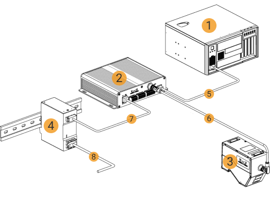
You need to mount and connect the hardware of the 3D measurement system, as shown below.
Prepare Materials
Before setting up the hardware, prepare the following materials.
1 |
IPC |
2 |
Controller |
3 |
Sensor head |
4 |
DIN rail power supply (optional) |
5 |
Controller Ethernet cable |
6 |
Sensor-head-to-controller cable |
7 |
DC power cable |
8 |
AC power cable (prepared by yourself) |
Mount the Laser Profiler
When mounting the laser profiler, follow these steps:
-
Mount the Sensor Head
-
Mount the Controller
-
Connect the Sensor Head and Controller
-
Connect the Controller and IPC
-
Connect the Controller and DIN Rail Power Supply
-
Connect the Controller and External Device
-
Set the Laser Profiler IP Address
For detailed instructions on mounting and connection, refer to Mounting and Connection in the getting started tutorial of the laser profiler.
Mount the IPC
| The IPC is normally mounted in the control cabinet. The environment in which the IPC is mounted requires good heat dissipation, ventilation, and dust-proof. It should be mounted at a location where Ethernet cables, HDMI cables, and USB ports can be easily mounted and maintained. |
For mounting of the Mech-Mind IPC STD model, refer to Mech-Mind IPC STD User Manual.
For mounting of the Mech-Mind IPC ADV model, refer to Mech-Mind IPC ADV User Manual.
After mounting the IPC, please start it. Make sure that the Mech-Eye SDK and Mech-MSR software used in the 3D measurement and inspection solution are running the latest versions.
If these software are not running the latest version, refer to the following documents to upgrade the software:
Connect the Network
In this section, you need to complete the Ethernet cable connection and network setup between the laser profiler and the IPC, as well as between the IPC and the external device.
Please pay attention to the following requirements when setting up the network:
-
The IP addresses of the laser profiler and the IPC’s Ethernet port connected to the laser profiler are in the same subnet.
-
The IP address of the external device and the IPC’s Ethernet port connected to the external device are in the same subnet.
Connect the IPC and External Device
The connection between the laser profiler (controller) and the IPC has been completed during the “Mount the Laser Profiler” step. Here, you need to connect the IPC and the external device.
Use an RJ45-to-RJ45 Ethernet cable to plug one end into the Ethernet port of the IPC and the other end into an Ethernet port of the external interface.
Set the IP Addresses on the IPC
-
Select on the IPC. The Network Connections page will be displayed.
-
Right-click the Ethernet port connected to the laser profiler, and select Rename to rename the Ethernet port, such as “To_profiler”.
-
Right-click the Ethernet port connected to the laser profiler, and select Properties to enter the Ethernet Properties page.
-
Select the Internet Protocol Version 4 (TCP/IPv4) checkbox, and then click the Property button to enter the Internet Protocol Version 4 (TCP/IPv4) Properties page.
-
Select the Use the following IP address radio button, set the IP address to “192.168.100.10”, Subnet mask to “255.255.255.0”, and Default gateway to “192.168.100.1”, and then click the OK button.
-
Repeat steps 2 to 5 to rename the Ethernet port connected to an external device (such as “To_external”), and set the IP address of the Ethernet port. For example, the IP address of this Ethernet port is “192.168.200.10.”
Test the Network Connectivity
-
Press Win + R to open the Run dialog box.
-
Type
cmdin the Run dialog box, and then click OK. -
Type ping XXX.XXX.XX.XX in the command prompt window and press Enter to execute the command.
Replace XXX.XXX.XX.XX with the actual IP address of the laser profiler or external device.
If the network connectivity is normal, you should receive the following response:
Pinging XXX.XXX.XX.XX with 32 bytes of data:
Reply from XXX.XXX.XX.XX: bytes=32 time<1ms TTL=128
Reply from XXX.XXX.XX.XX: bytes=32 time<1ms TTL=128
Reply from XXX.XXX.XX.XX: bytes=32 time<1ms TTL=128
Reply from XXX.XXX.XX.XX: bytes=32 time<1ms TTL=128