Transform Surface
Description
Use this Step to transform the surface data to a new reference frame formed by input geometric features such as plane, line, and point.
Usage Scenario
This Step is commonly used in two scenarios: adjusting the inspection surface to the horizontal level and data alignment.
-
Adjust the inspection surface to the horizontal level
-
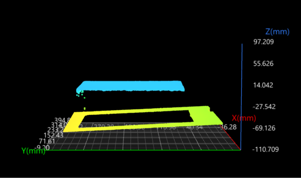
Function: The Step can adjust a tilted inspection surface to the horizontal level, i.e., making it parallel to the XOY plane.
-
Common scenario: During measurements, the depth values of data points are used for filtering.
-
Example transformation method: Plane.
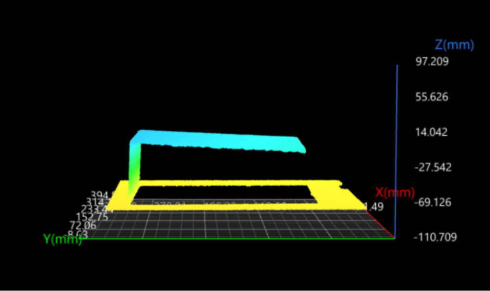
Tilted top surface
Transformed data
-
-
Data alignment
-
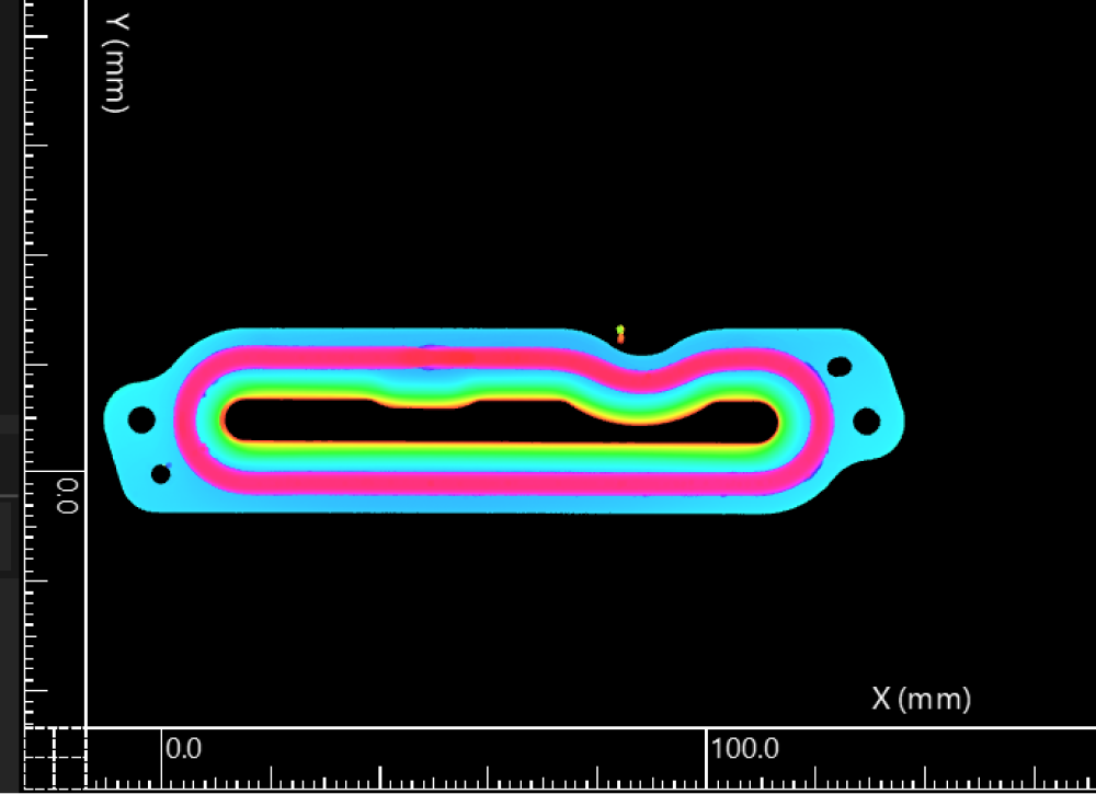
Function: For different incoming objects, the Step can ensure the target object’s position is the same in all images.
-
Common scenario: The target object is expected to be in a specified position in the image, and the point, line, and plane features can be easily and stably obtained.
-
Example transformation method: Plane + line + point.
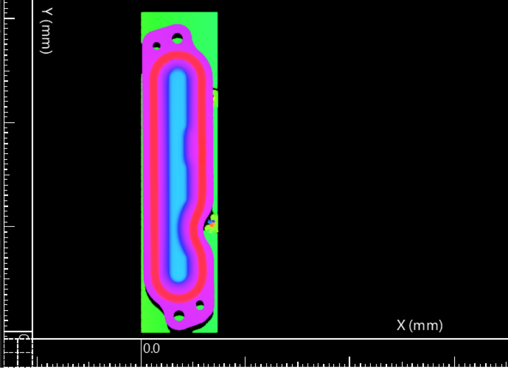
Before
After
-
Methods for Transforming Surface
The geometric features (point, line, plane) input into the Step determine the method for transforming the reference frame of the surface data.
The currently supported input combinations are as follows:
| When no geometric features are input into the Step, the surface data will be transformed according to the settings in the Parameters section. |
Plane
In the Input section, input a plane feature and leave the line and point features empty.
The reference frame in which the transformed surface data resides is as follows:
-
XOY plane: the input plane.
-
X-axis: The new X-axis is parallel to the original X-axis.
-
Origin: The origin of the original reference frame is projected onto the input plane, and the projection becomes the origin of the new reference frame.

Line
In the Input section, input a line feature, and leave the plane and point features empty.
The reference frame in which the transformed surface data resides is as follows:
-
XOY plane: The cross product of the input line and the normal vector of the original XOY plane defines the Y-axis of the new reference. The new Y-axis and the input line form the XOY plane.
-
X-axis: the input line.
-
Origin: The origin of the original reference frame is projected onto the input line, and the projection becomes the origin of the new reference frame.

Point
In the Input section, input a point feature, and leave the plane and line features empty.
The reference frame in which the transformed surface data resides is as follows:
-
XOY plane: The new XOY plane, passing through the input point, is parallel to the original XOY plane.
-
X-axis: The new X-axis is parallel to the original X-axis.
-
Origin: the input point.

Plane + Line
In the Input section, input a plane and a line, and leave the point feature empty.
The reference frame in which the transformed surface data resides is as follows:
-
XOY plane: the input plane.
-
X-axis: the projection of the input line onto the input plane.
-
Origin: The projection of the original reference frame’s origin onto the projection of the input line, i.e., the new X-axis.

Plane + Point
In the Input section, input a plane and a point, and leave the line feature empty.
The reference frame in which the transformed surface data resides is as follows:
-
XOY plane: the input plane.
-
X-axis: The new X-axis is parallel to the original X-axis.
-
Origin: The input point is projected onto the input plane, and the projection becomes the origin of the new reference frame.

Line + Point
In the Input section, input a line and a point, and leave the plane feature empty.
The reference frame in which the transformed surface data resides is as follows:
-
XOY plane: The cross product of the input line and the normal vector of the original XOY plane defines the Y-axis of the new reference. The new Y-axis and the input line form the XOY plane.
-
X-axis: the input line.
-
Origin: The input point is projected onto the input line, and the projection becomes the origin of the new reference frame.

Plane + Line + Point
In the Input section, input a plane, a line, and a point.
The reference frame in which the transformed surface data resides is as follows:
-
XOY plane: the input plane.
-
X-axis: the projection of the input line onto the input plane.
-
Origin: The input point is projected onto the input line, and the projection becomes the origin of the new reference frame.

Workflow
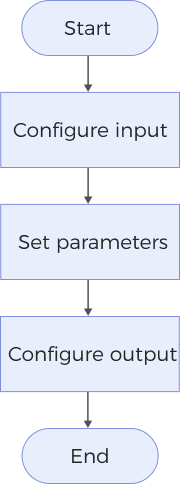
The process of configuring this Step is as follows:
-
Configure the input. Connect the Step ports in the graphical programming workspace or select the input under Input in the parameter configuration panel.
-
Determine whether to use a feature region. See Feature Region to learn about the settings.
-
In the Parameters section, determine whether to add fixed transformations or not and set the resolution mode.
-
Select the desired output items under Output. For an expandable output item, click ▶ and configure the Min and Max values to determine the acceptable range for the item.
Parameter Description
| Parameter | Description | ||
|---|---|---|---|
Use Feature Region |
After selecting this parameter, you need to set the feature region to limit the surface data used by the Step. See Feature Region to learn about how to adjust a feature region. When this parameter is unselected, the Step will use the entire surface data. |
||
Add Fixed Transformations |
Select this parameter to add fixed transformations. After the surface data is transformed to a new reference frame according to the geometric features input into the Step, the added fixed transformations can be applied. The description of the fixed transformation parameters is as follows:
|
||
Resolution Mode |
Use this parameter to determine whether to scale the X-axis and Y-axis resolution of the transformed surface in a 1:1 ratio. You can select one of the following modes:
|
Output Description
The output of this Step is transformed surface data that can be used as input into other Steps.
Troubleshooting
|
CV-W3604
Error: The set axial translation parameters are invalid.
Solution: Verify that the set values of the axial translation parameters are valid.
CV-W3605
Error: The set rotation angle about the X/Y/Z-axis is invalid.
Solution: Verify that the set rotation angles about the X/Y/Z-xis are valid.
CV-W3606
Error: The set “Resolution Mode” is invalid.
Solution: Select a valid resolution mode from the drop-down list.
CV-W3607
Error: Failed to calculate the X-axis of the new reference frame.
Possible causes:
-
The input geometric features are a line and a plane, and the line is perpendicular to the plane.
-
The input geometric feature is a plane, and the plane is parallel to the original XOZ plane.
Solutions:
-
When the input geometric features are a line and a plane, ensure the line is not perpendicular to the plane.
-
When the input geometric feature is a plane, ensure the plane is not parallel to the original XOZ plane.