Filter Surface Points by Normals
Description
This Step is used to exclude unwanted surface points by their normals so that a better surface can be obtained.
|
|
Before filtering |
After filtering |
Workflow
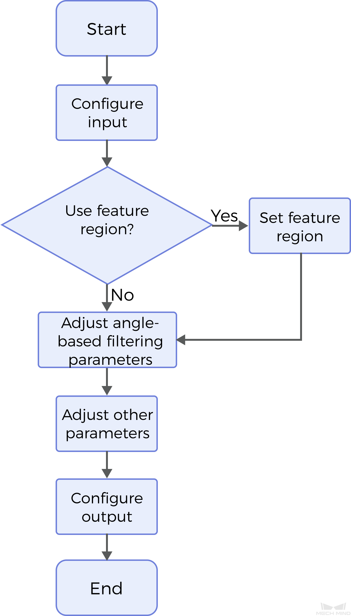
The process of configuring this Step is as follows:

-
Configure the input. Connect the Step ports in the graphical programming workspace or select the input under Input in the parameter configuration panel.
-
Determine whether to use a feature region. For more information, see Use Feature Region.
-
Set the angle parameters.
-
Set other parameters.
-
Select the output item Surface Data (selected by default).
Parameter Description
First, it is necessary to determine whether to select Use Feature Region. The feature region is used to define the area for surface point filtering.
-
Unselected (default): The Step will process the entire surface data.
-
Selected: Only data within or outside the feature region will be processed. At this point, the following parameters need to be set:
Parameter Description Feature Region Mode
This parameter is used to set the mode of the feature region, that is, to select whether to filter the surface data within the feature region or to filter the data outside the feature region.
Options: Include data in Region, Exclude data in Region
Feature Region
See Feature Region to learn about how to adjust a feature region.
Keep Unfiltered Data
Once this parameter is selected, the unfiltered data will be retained in the output. Unselected by default.
Then, set parameters related to Angle-Based Filtering and Normal Vector Calculation based on the actual needs.
Angle-Based Filtering
 |
|---|
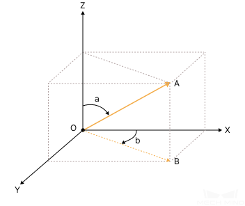
As shown in the figure above, OA is the normal, and OB is the XOY projection of OA; ∠a is the polar angle of OA while ∠b is the Z angle of OA. |
| Parameter | Description | ||
|---|---|---|---|
Min Polar Angle |
The minimum acceptable angle of the normals with respect to the Z-axis. |
||
Max Polar Angle |
The maximum acceptable angle of the normals with respect to the Z-axis. |
||
Min Z Angle |
The minimum acceptable angle of the XOY projection of normals clockwise around the Z-axis and relative to the positive X direction. |
||
Max Z Angle |
The maximum acceptable angle of the XOY projection of normals clockwise around the Z-axis and relative to the positive X direction.
|
||
Remove Noise |
As noise can be introduced by normal calculation, select the noise removal level according to the tolerance to noise. Options: None, Small, Medium, Large |
||
Smooth Size |
The size of the filter window. Apply a mean filter to the surface data before calculating the normals to avoid abrupt normal changes due to noise. The default value is 1. |
Normal Calculation
| Parameter | Description |
|---|---|
Normal Search Radius |
Points within a circle with the set search radius will be used to calculate normals. The unit is millimeters (mm). The default value is 1.000. |
Half Kernel Size |
Points within a square with a side length twice the set half kernel size will be used to calculate the normals. The unit is pixels(px), and the default value is 1. |
Output Description
The output of this Step is a processed depth map that can be used as input to other Steps.
Troubleshooting
|
CV-W3001
Error: The “Smooth Size” value is less than 1.
Possible cause: The “Smooth size” value is less than 1.
Solution: Reset "Smooth Size" and ensure that the value exceeds 1.
CV-W3002
Error: The set polar angle is not within the range of 0–90°.
Possible cause: The set polar angle is not within the range of 0–90°.
Solution: Reset the polar angle to ensure that the polar angle is within the range of 0–90°.
CV-W3003
Error: The set Z angle is not within the range of 0–360°.
Possible cause: The set Z angle is not within the range of 0–360°.
Reset Min / Max Z Angle to ensure that the Z angle is within the range of 0–360°.

